|
|
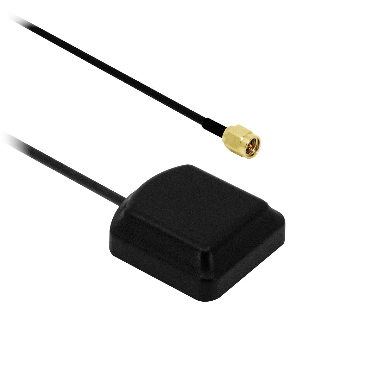
¶ General Description
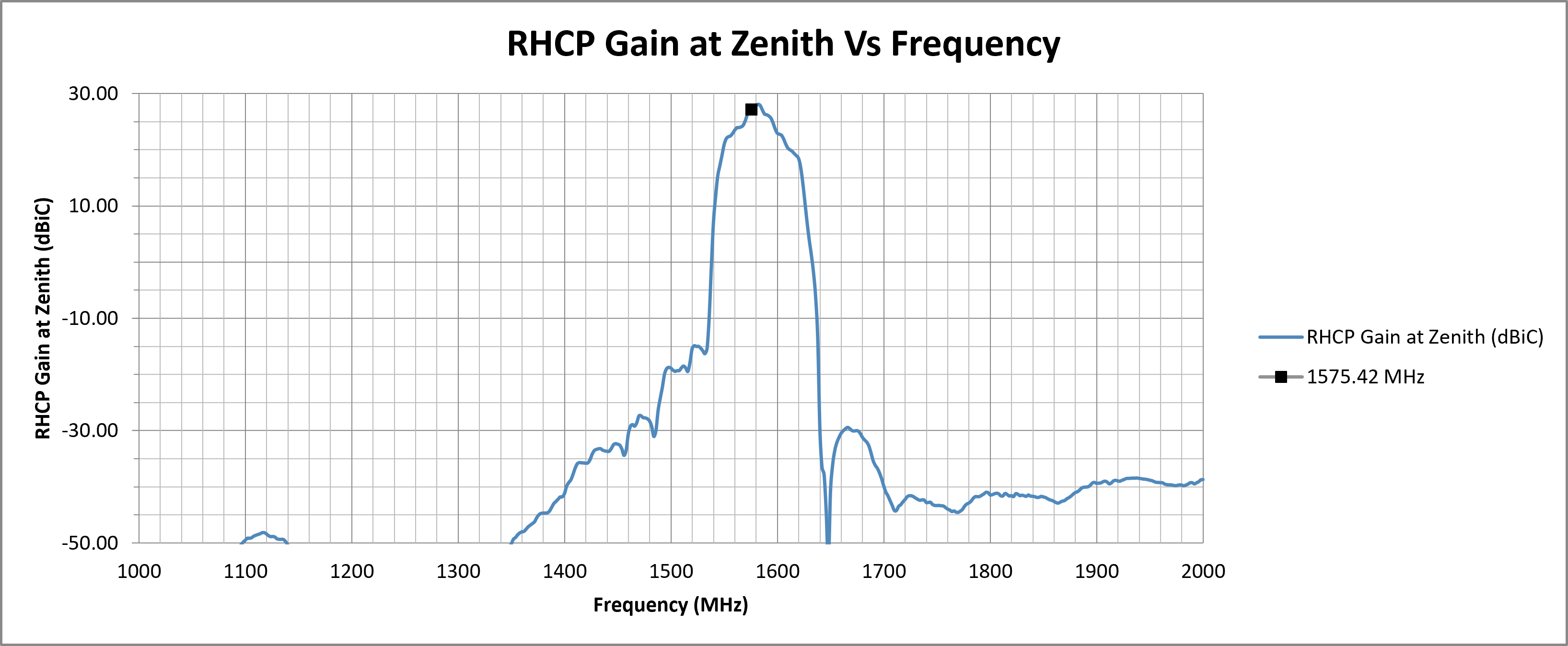
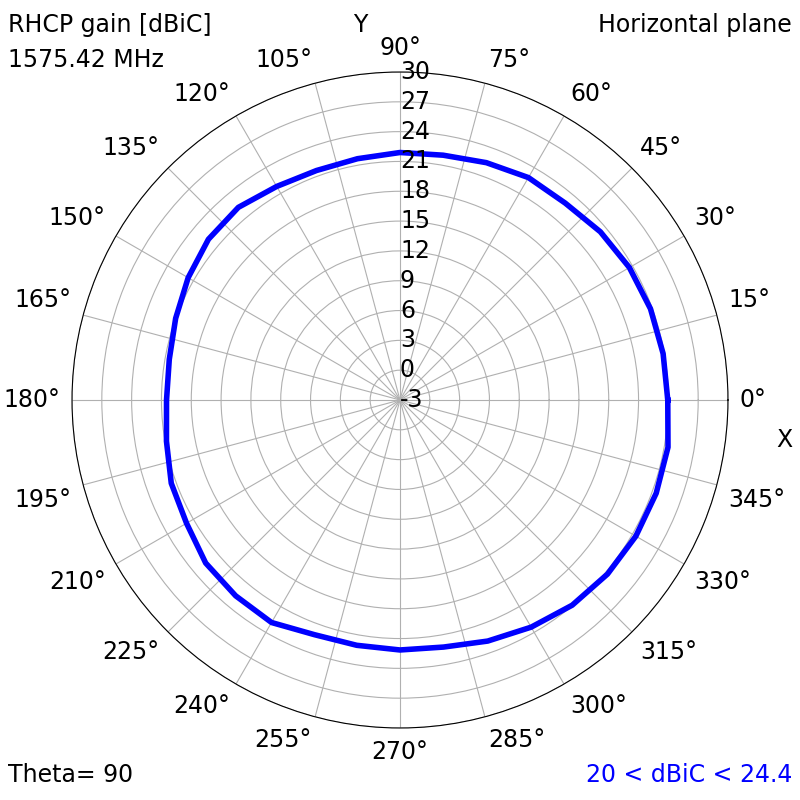
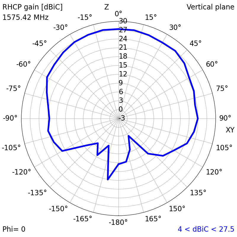
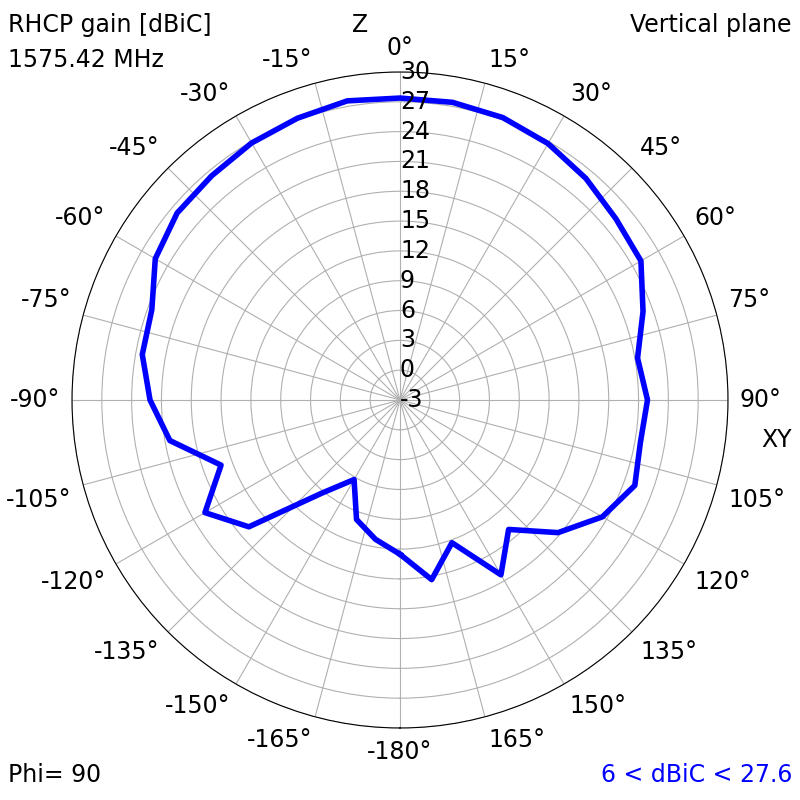
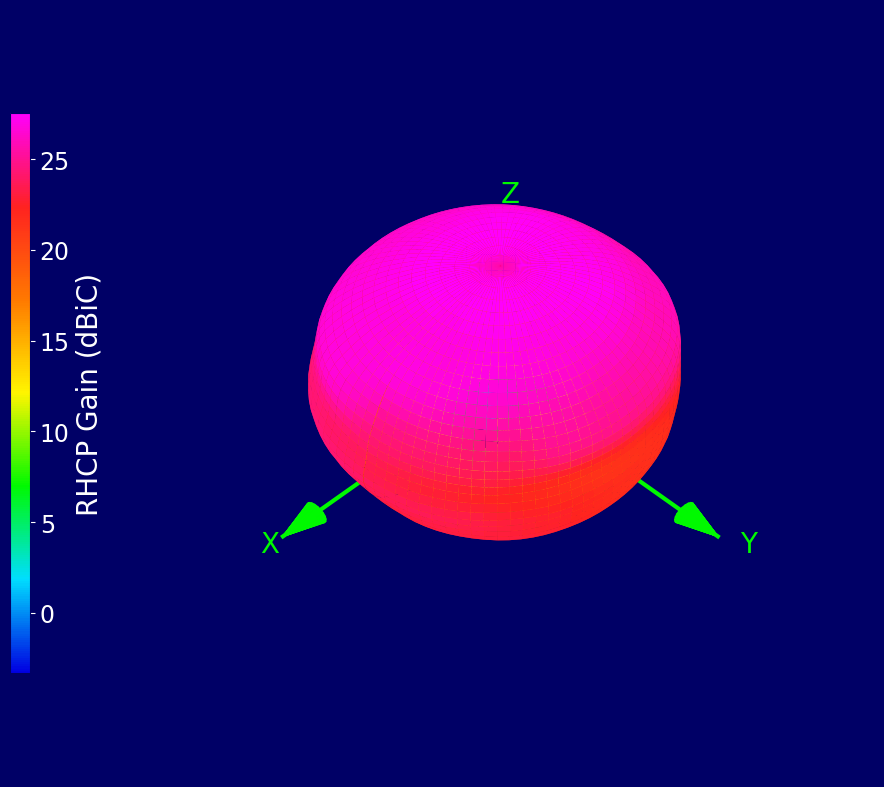
The Alpha 4A is a compact, waterproof, self-adhesive GPS antenna designed for reliable L1-band performance. Delivering strong RHCP gain of 27.6 dBiC at zenith, the Alpha 4A also maintains excellent top-hemisphere uniformity with consistent performance across 90° and 120° angular sectors from zenith.This gain stability ensures dependable satellite visibility and reduced fix times in outdoor environments. The integrated low-noise amplifier (26 ± 2 dB) enhances weak signals, providing a reliable performance for vehicle tracking, fleet management, asset monitoring, and GNSS timing systems.
Supplied as standard with SMA Male connectors and 1 m or 5 m RG174 cable.
Alternative cable lengths and connector types can be specified for high-volume projects.
¶ Key Features
- Supports GPS L1, Galileo E1, BeiDou B1C, and QZSS L1
- High RHCP gain 20–28 dBiC
- Consistent coverage across ±90° and ±120° from zenith
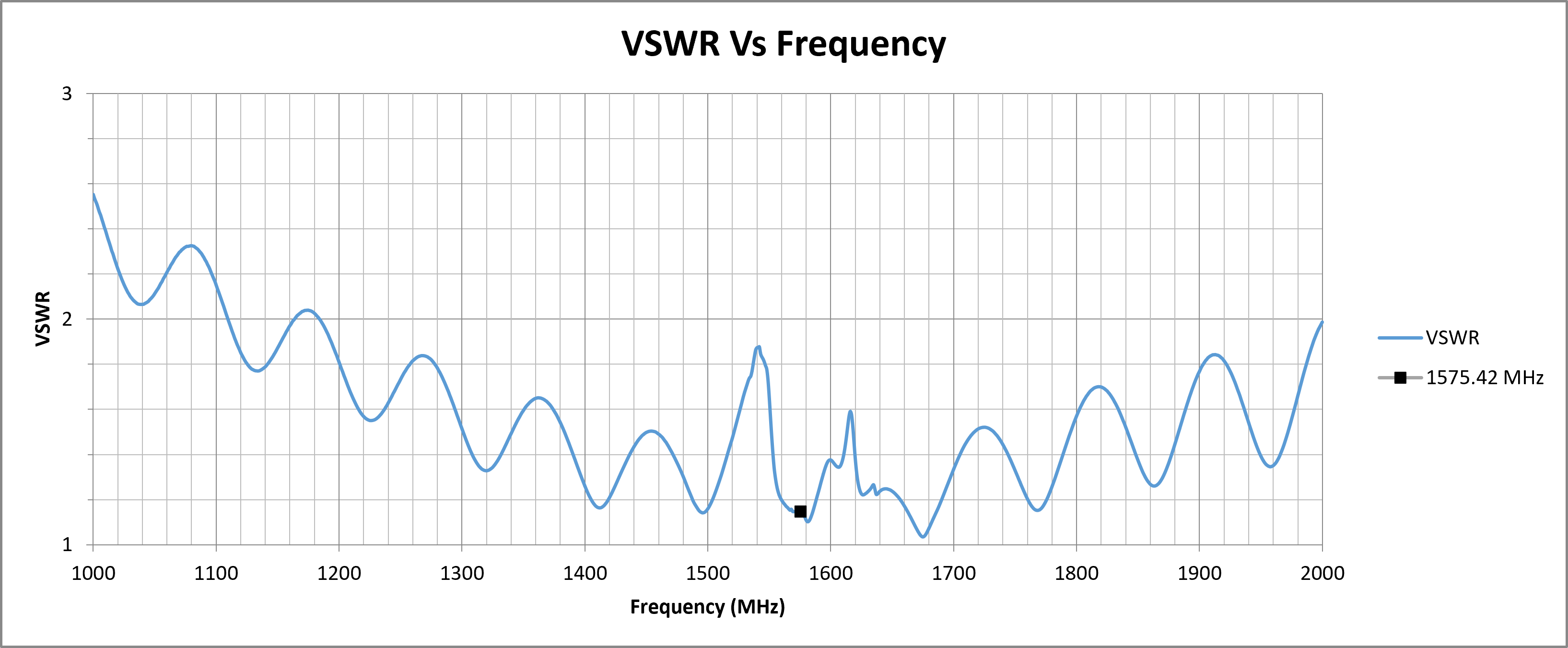
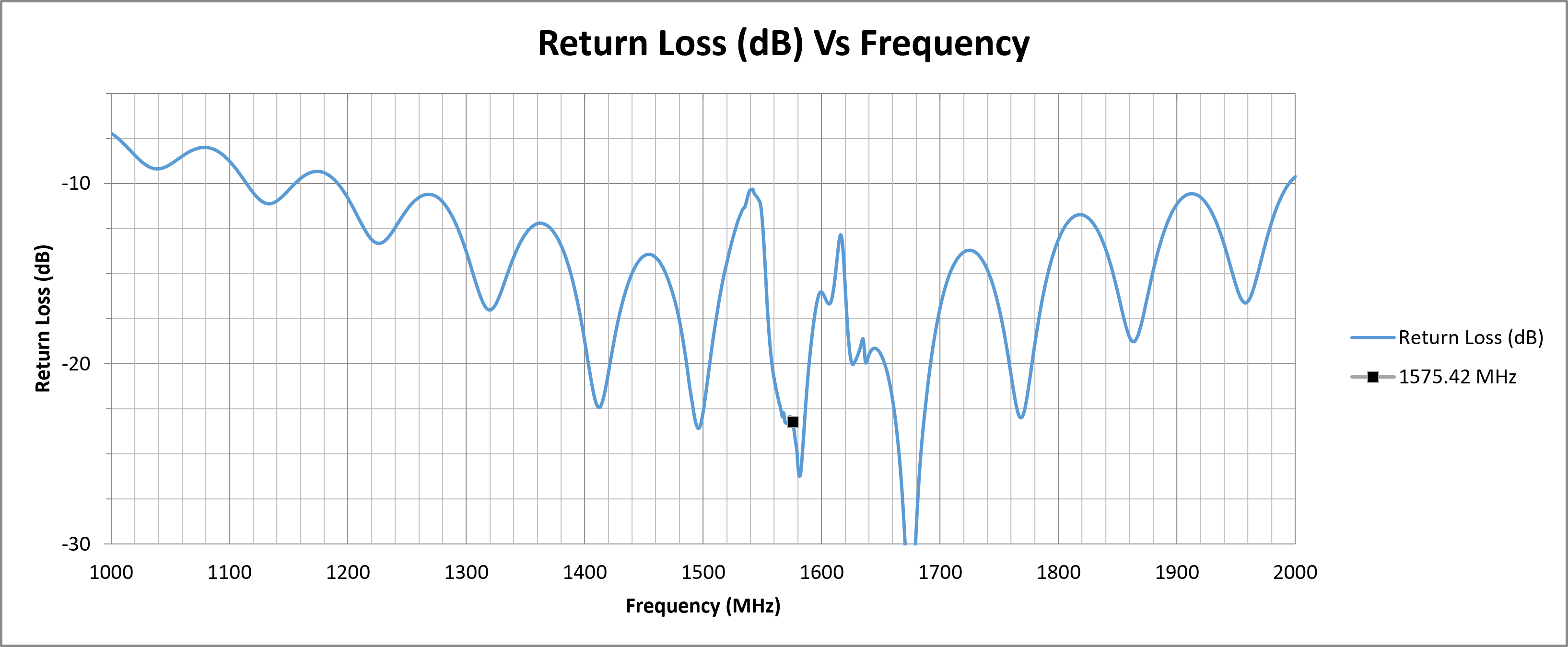
- Low VSWR (1.15 typical) with excellent return loss (−23 dB)
- Integrated 26 ± 2 dB LNA with ≤ 1.3 dB noise figure
- Compact IP67 waterproof design with adhesive or optional magnetic mount
¶ Typical Applications
- Vehicle and fleet tracking
- Asset monitoring and telematics
- Outdoor GNSS positioning and timing
- Smart infrastructure and IoT
|
GPS L1 Antenna
Active GNSS
|
Water Resistant
Outdoor Radome
|
RHCP Gain
20–28 dBiC
|
Magnetic Mounting
Quick Installation
|
Low-Profile Design
Compact Installation
|
¶ Electrical Specifications
| Impedance: | 50 Ohm |
| Polarisation: | RHCP |
| Frequency Range: | 1575.42 MHz |
| Return Loss: | -23.21 dB |
| VSWR: | 1.15 typ. |
| Required Ground Plane: | 100 x 100 mm |
| Peak RHCP Gain (Top Hemisphere): |
27.58 dBiC |
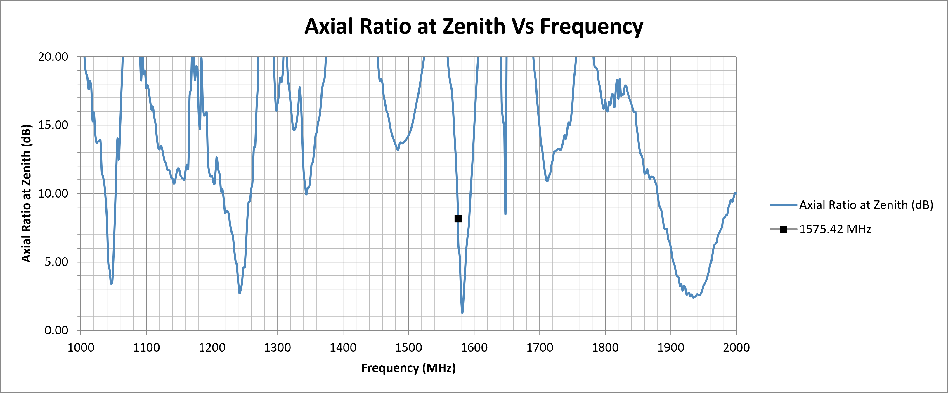
| Axial Ratio at Zenith: | 8.17 dB |
| LNA Gain: | 26 ± 2 dB |
| Noise Figure: | ≤ 1.3 dB |
| Supply Voltage: | 2.5 - 5 V DC |
| Current Consumption: | 10–26 mA |
¶ Environmental Specifications
| Operating Temperature Range: | -40°C to 80°C |
| Storage Temperature Range: | -40°C to 80°C |
| Relative Humidity: | Up to 95% |
| Ingress Protection: | IP67 |
¶ Mechanical Specifications
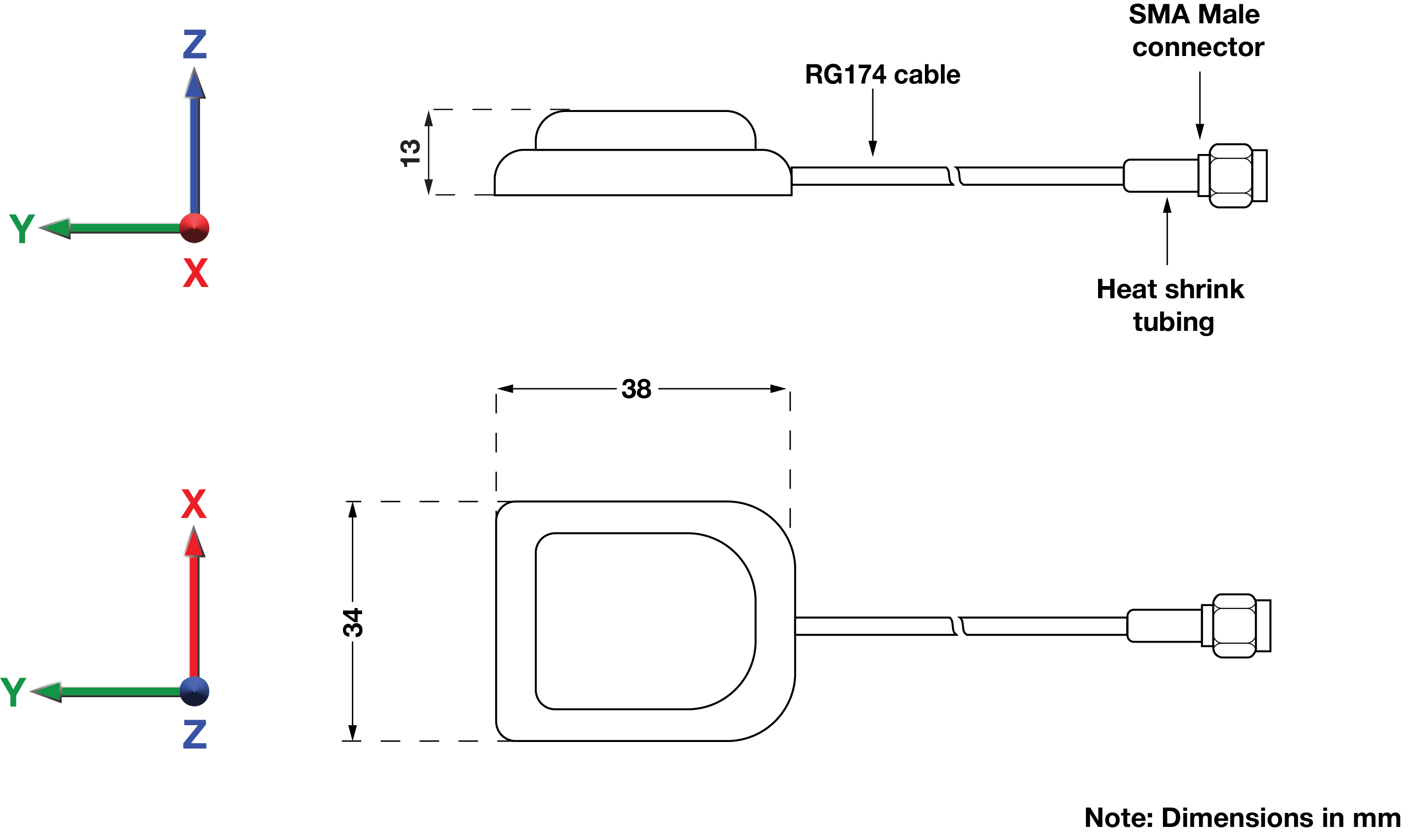
| Dimensions: | L = 38 mm W = 34 mm H = 13 mm |
| Weight: | 33 g |
| Cable Type: | RG174 |
| Cable Length: | 1 m, 5 m or alternative |
| Connector: | SMA Male |
| Mounting method: | Adhesive (magnetic available for high-volume projects) |
¶ Spectrum Coverage*
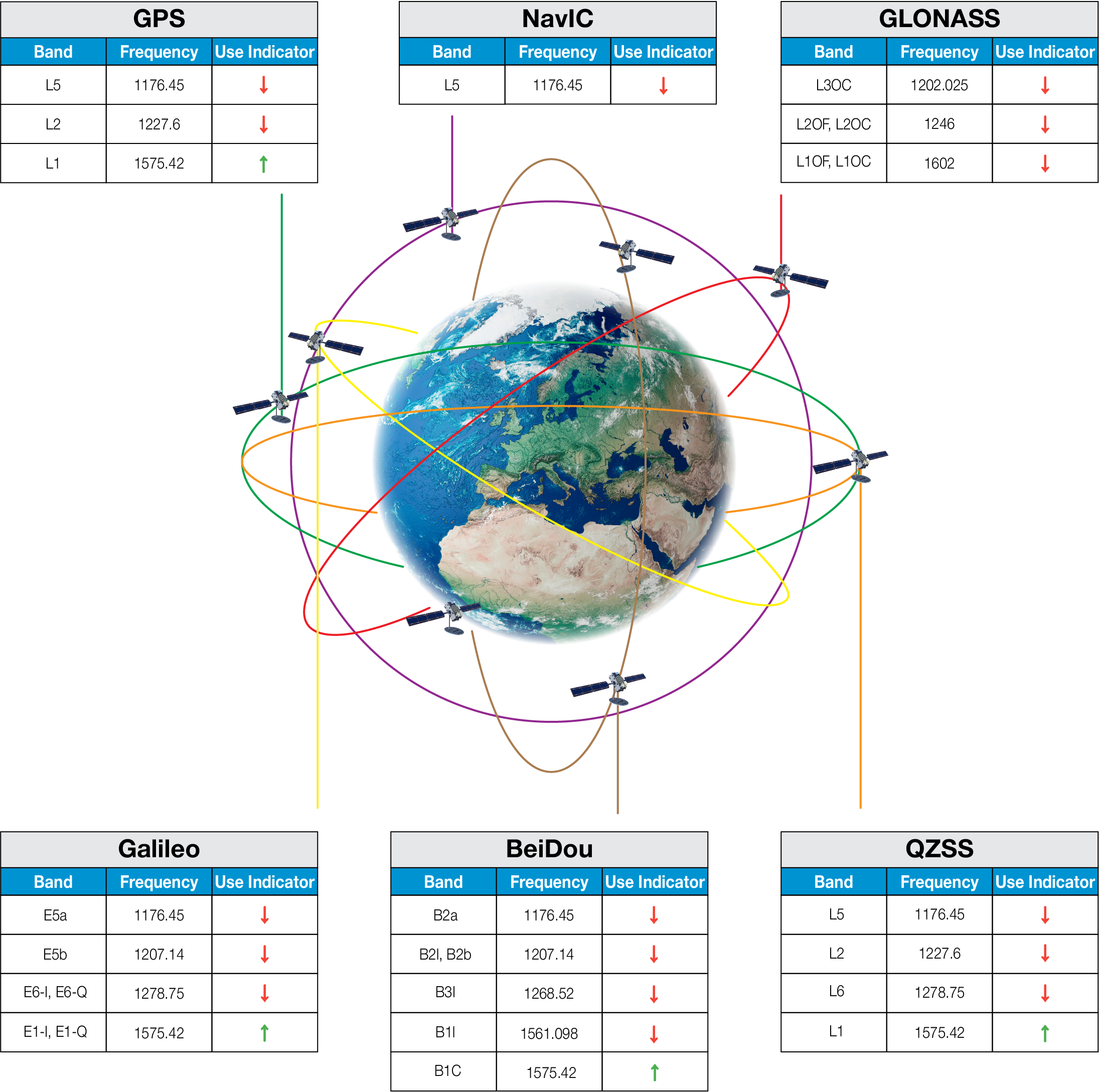
| ↑ Suitable band | □ Adequate band in good signal conditions | ↓ Likely to be unsuitable |
¶ GNSS Standards Band Support
| Electrical Interface | Spherical RF Measurements | |||||
|---|---|---|---|---|---|---|
| Centre Frequency (MHz) | VSWR | Return Loss (dB) | Average RHCP Gain (dBiC) | Peak RHCP Gain (dBiC) | Median Axial Ratio (dB) | Minimum Axial Ratio (dB) |
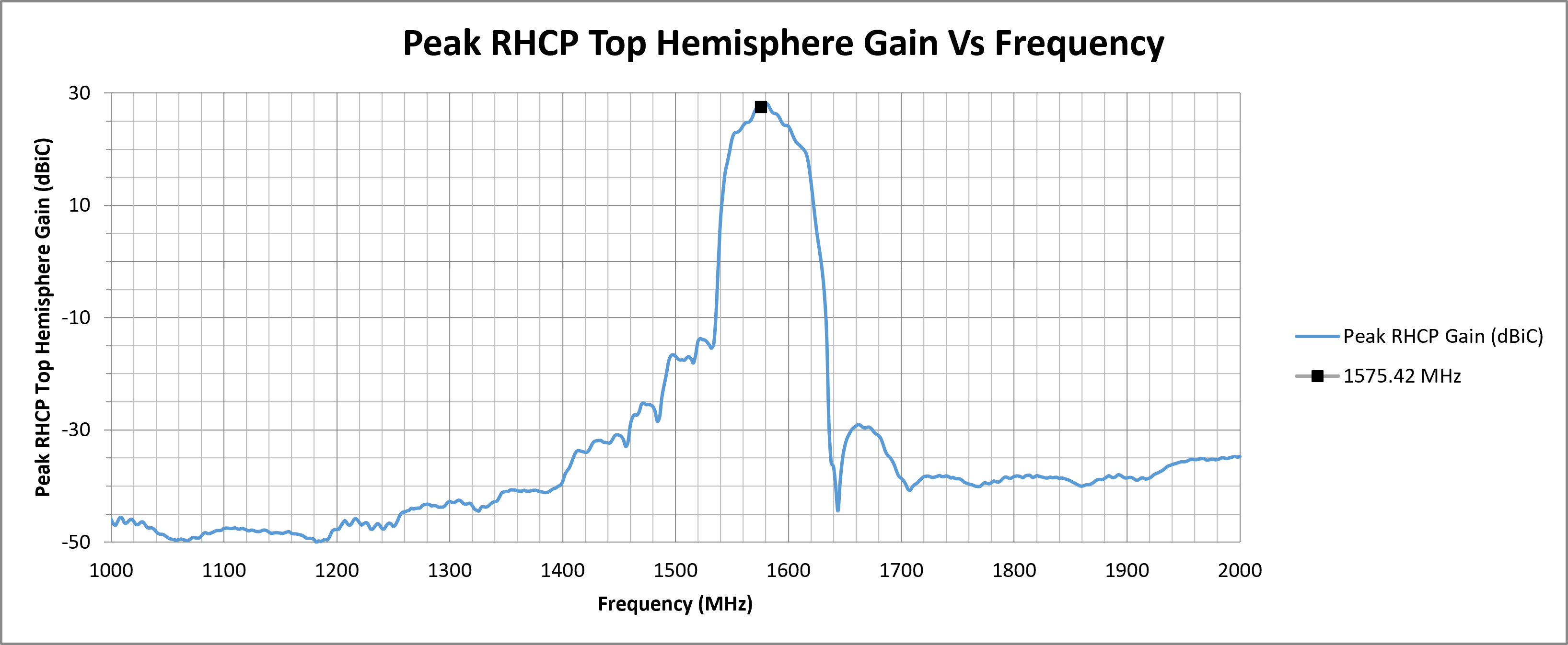
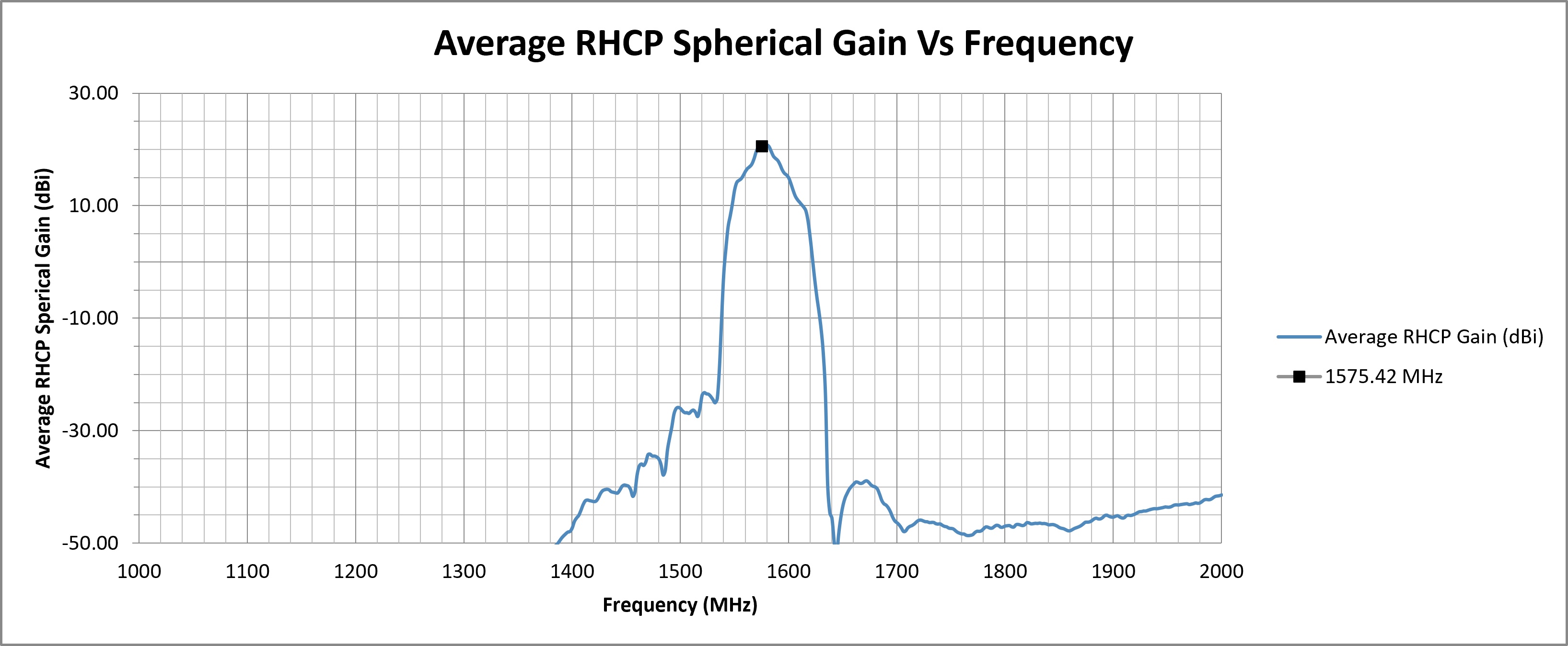
| 1575.42 (L1) | 1.1485 | -23.2122 | 20.57 | 27.58 | 5.80 | 0.44 |
| Top Hemisphere RF Measurements | Zenith RF Measurements | |||||
|---|---|---|---|---|---|---|
| Centre Frequency (MHz) | Average RHCP Gain (dBiC) | Peak RHCP Gain (dBiC) | Median Axial Ratio (dB) | Minimum Axial Ratio (dB) | RHCP Gain at Zenith (dBiC) | Axial Ratio at Zenith (dB) |
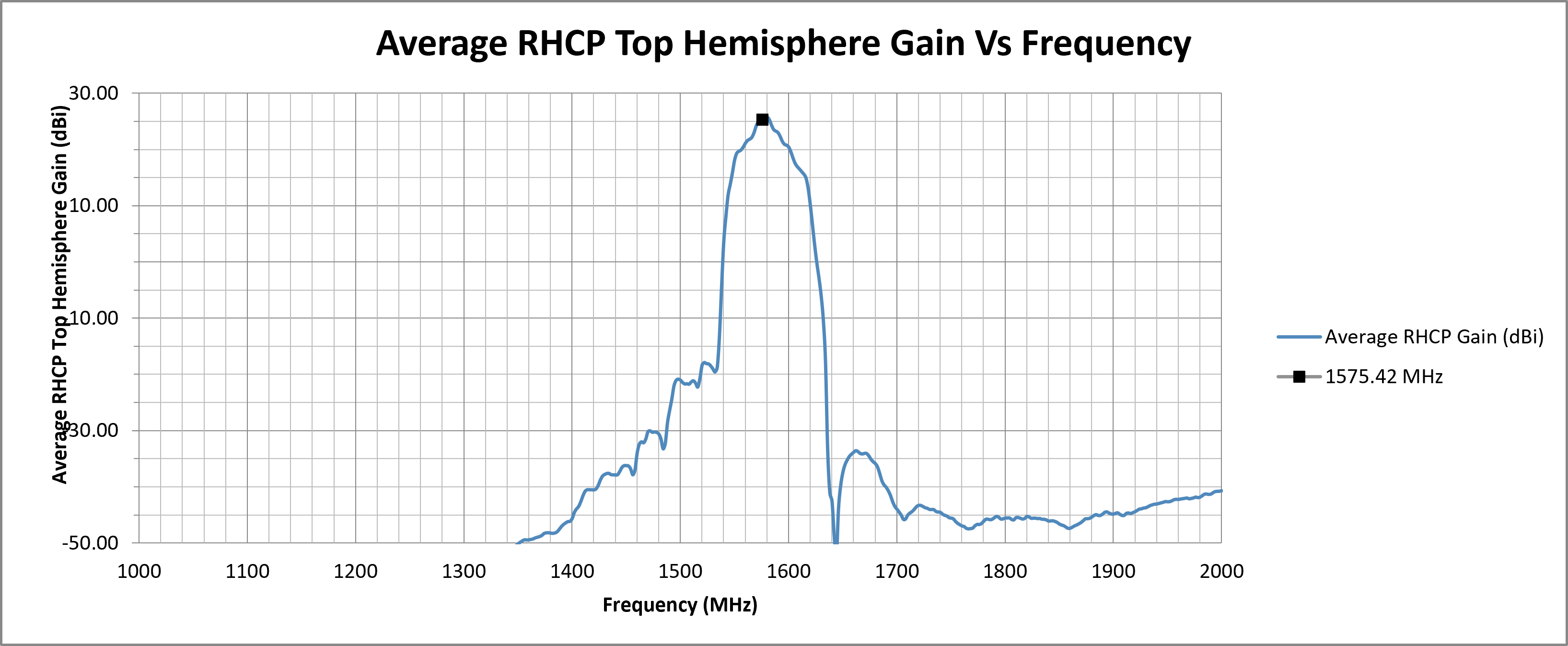
| 1575.42 (L1) | 25.36 | 27.58 | 5.46 | 1.77 | 27.22 | 8.17 |
¶ RF Matching Performance
This section illustrates the antenna's impedance matching characteristics across the operating frequency range using VSWR and Return Loss measurements.
¶ RF Zenith
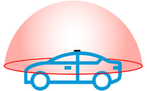
¶ RF Top Hemisphere
¶ RF Spherical
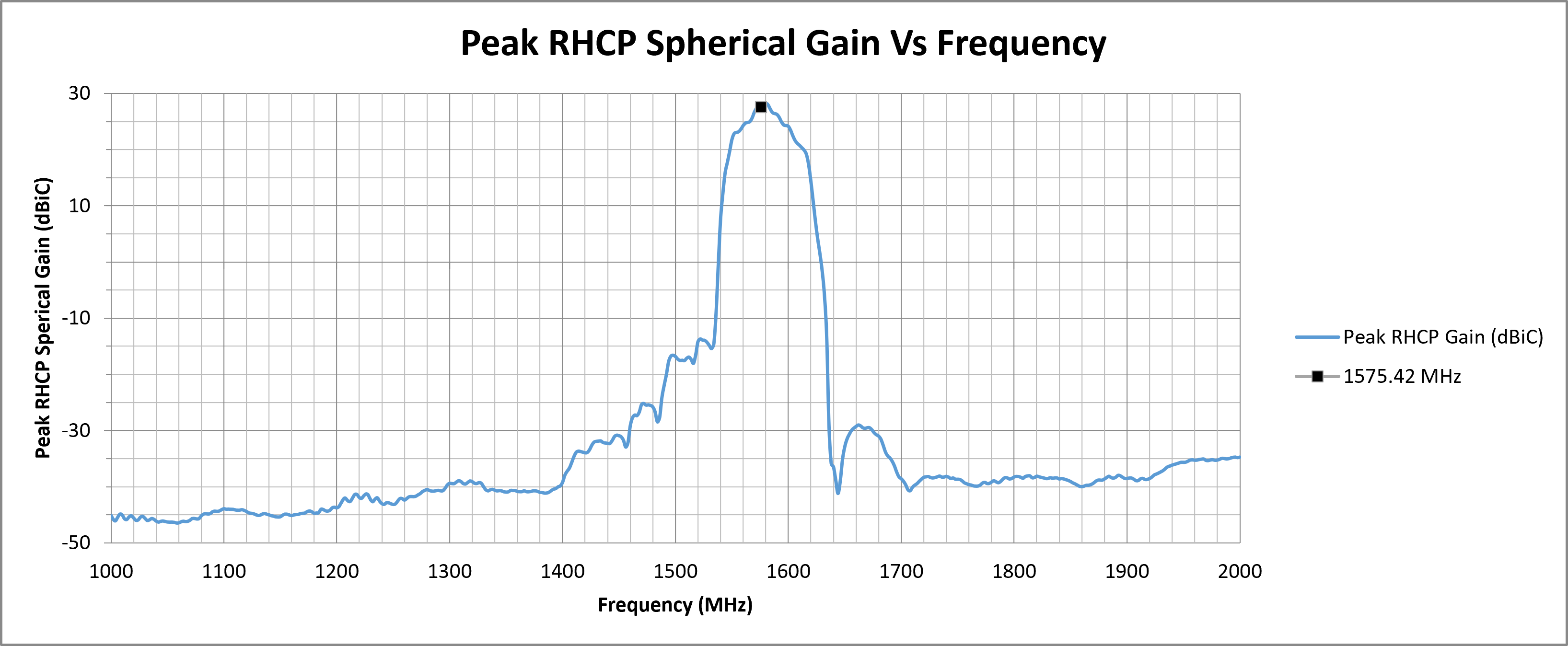
The following graphs display the Average and Peak RHCP Gain across the entire spherical coverage of the antenna. These metrics provide a comprehensive view of the antenna’s ability to receive signals from satellites at all elevations and directions.
Consistently high gain across the sphere ensures strong and stable GNSS reception in a variety of operating conditions.

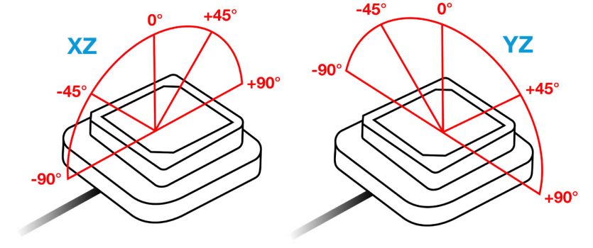
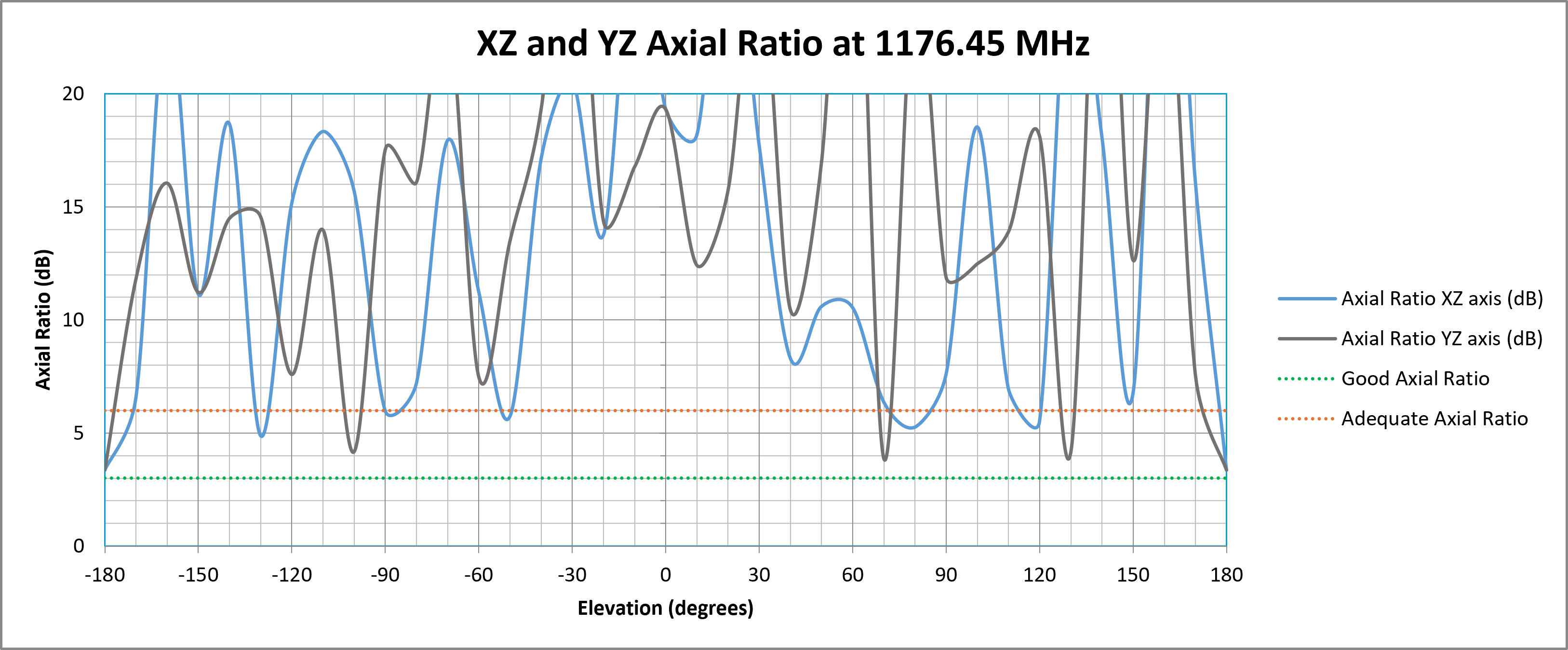
¶ ZX and YZ Plane Axial Ratio Plots (Zenith is at 0 degrees)
The following graph shows how well the antenna maintains circular polarisation at different elevation angles. A lower axial ratio ensures better GNSS signal reception, especially at low elevations, which is crucial for applications requiring strong performance in obstructed environments or wide-angle satellite visibility.
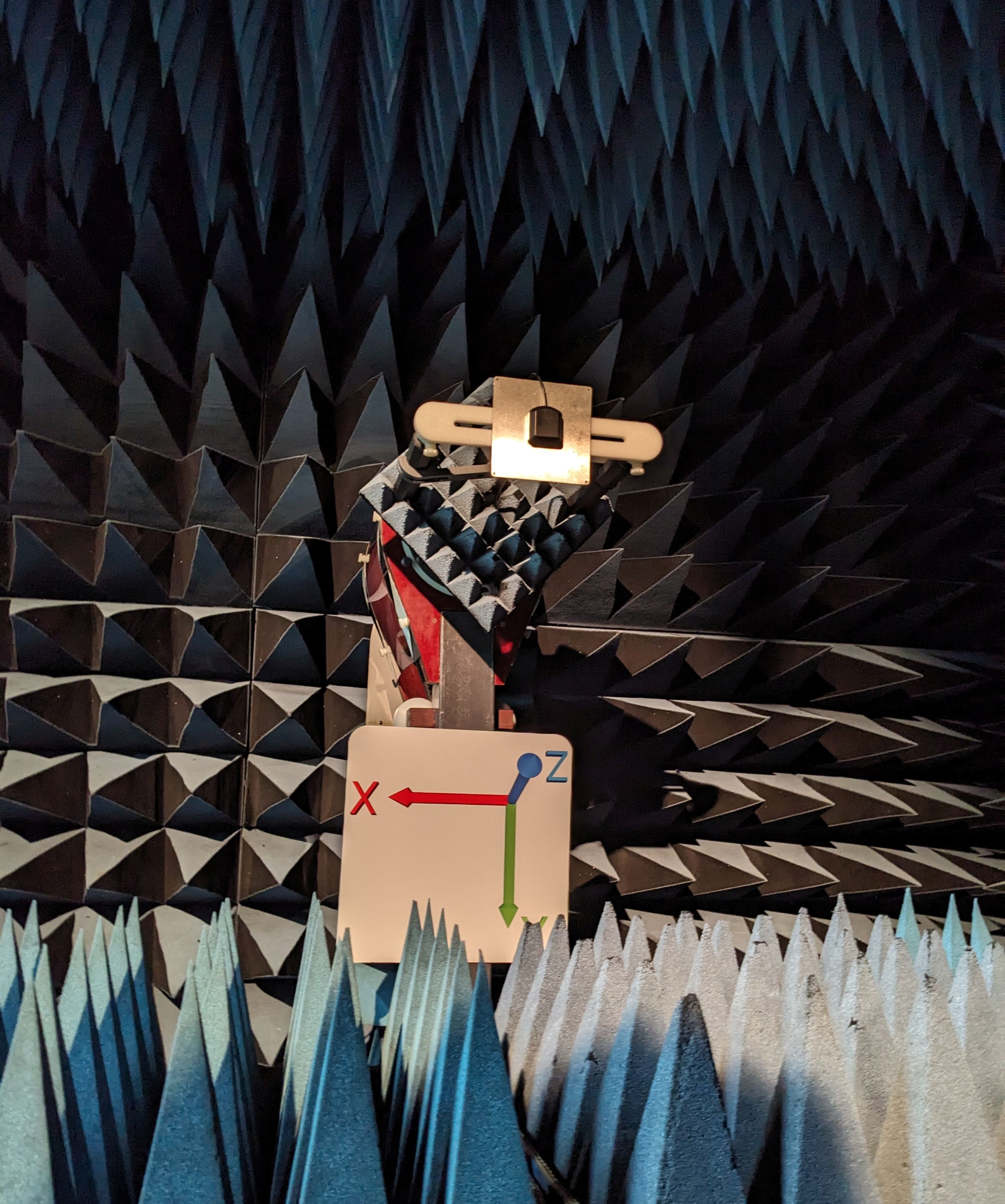
¶ Test Setup (on 100 x 100 mm Ground Plane)
¶ 2D Radiation Plots
1575.42 MHz (L1)
|
|
|
¶ 3D Radiation Plots
1575.42 MHz (L1)
¶ Ordering Details
| Part Number | Description |
|---|---|
| ALPHA4A/1M/SMAM/S/S/26 |
Compact Wide-Angle Active GPS L1 Adhesive Antenna 1 Metre RG174 Cable and SMA Male Connector |
| ALPHA4A/5M/SMAM/S/S/26 |
Compact Wide-Angle Active GPS L1 Adhesive Antenna 5 Metre RG174 Cable and SMA Male Connector |