|
|
¶ General Description
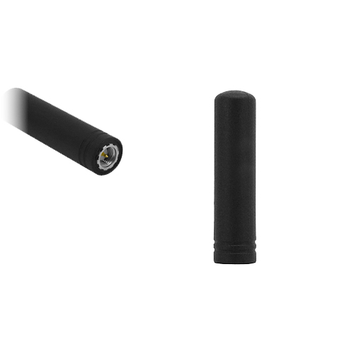
The Delta 60 is a compact, stubby terminal-
mount GNSS antenna designed for direct
connection via its SMA male connector. The
antenna integrates a 4-axis ceramic helix with
an active low noise design, providing reliable
right-hand circularly polarised gain across the
top hemisphere for strong satellite reception
and reduced fix times.
Encapsulated in a rugged TPU housing, the
Delta 60 is well suited to demanding outdoor
and mobile environments. Its lightweight,
space-efficient design makes it an ideal
choice for vehicles, handheld receivers, IoT
trackers and portable navigation devices.
Supplied as standard with an SMA male
connector. Alternative connector types can be
specified for high-volume projects.
¶ Key Features
- GPS L1 band support (1575.42 MHz)
- 24 dBiC RHCP gain
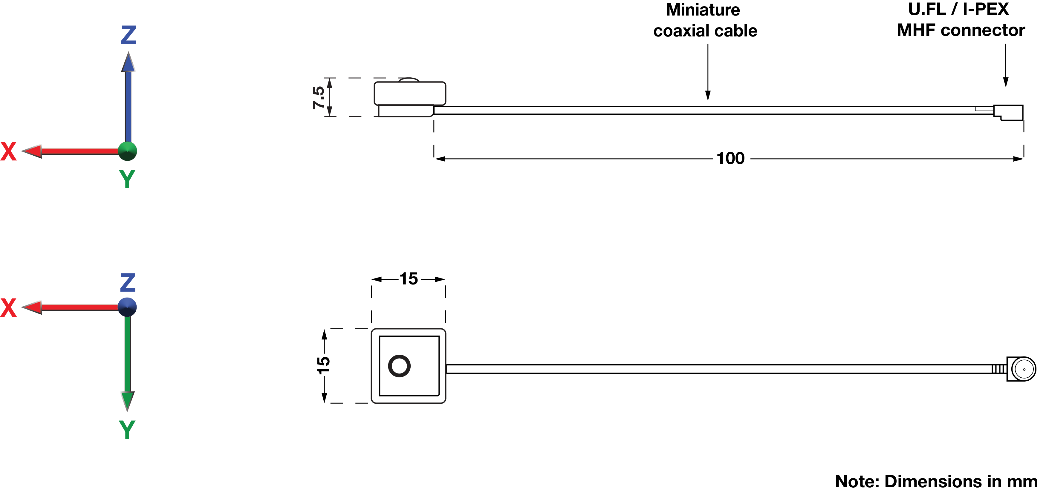
- Compact 15 × 15 × 7.45 mm embedded form factor
- Low voltage, low current design for power-sensitive devices
- Ceramic filter to suppress out-of-band noise
¶ Typical Applications
- IoT and asset tracking devices
- UAVs and drones
- Portable GNSS receivers
- Compact navigation modules
- Wearable GPS equipment
|
Multi-Band GNSS
1176–1602 MHz
|
Active Antenna
Integrated LNA
|
RHCP Gain
≤ 39 dBiC
|
QFH Design
Low-Elevation Reception
|
Compact Direct Mounting
Simple Installation
|
¶ Electrical Specifications
| Impedance: | 50 Ω |
| Polarisation: | RHCP |
| Frequency Range: | 1575.42 MHz |
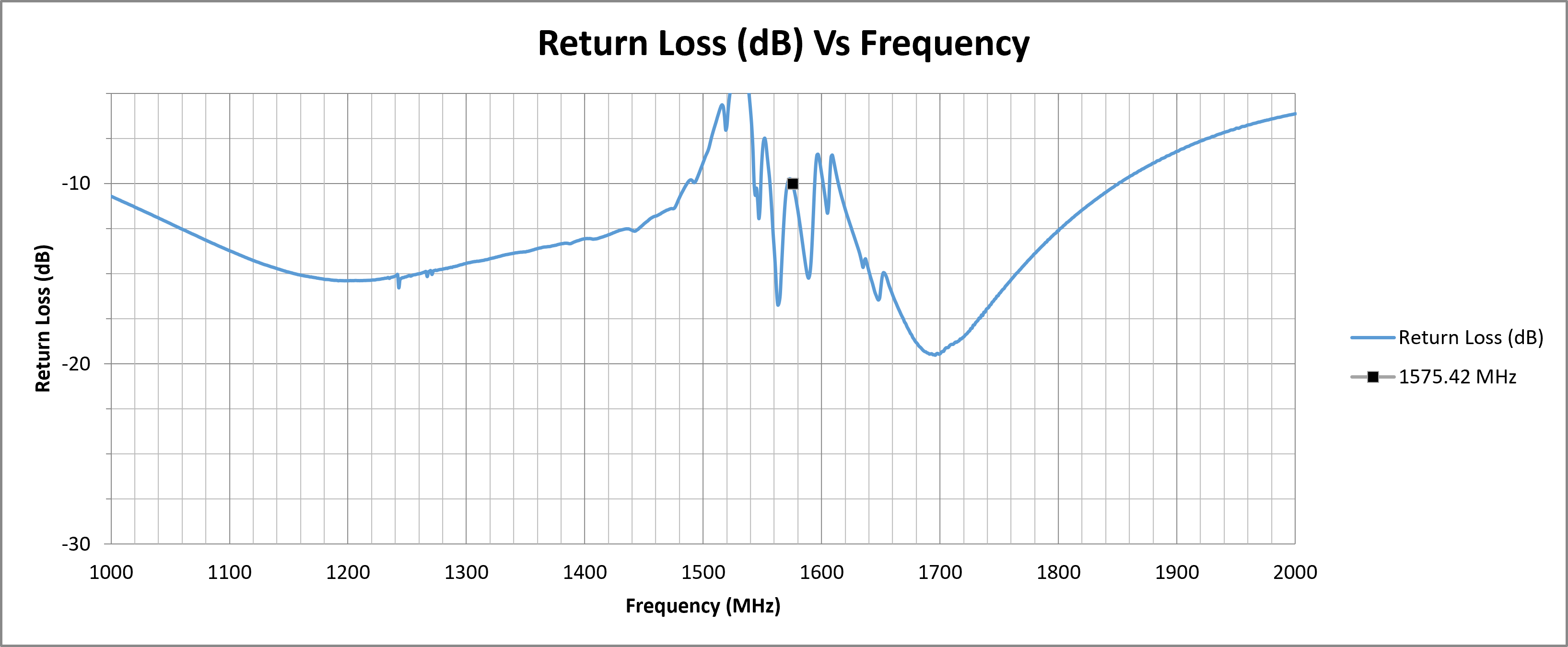
| Return Loss: | −10 dB |
| VSWR: | < 2 |
| Required Ground Plane: | 100 x 100 mm |
| Peak RHCP Gain (Top Hemisphere): |
24.15 dBiC |
| LNA Gain: | 27 dB |
| Noise Figure: | 1.5 dB typ. |
| Supply Voltage: | 2.3 – 5.5 V DC |
| Current Consumption: | 6.6 – 16 mA |
¶ Environmental Specifications
| Operating Temperature Range: | −40 °C to 90 °C |
| Storage Temperature Range: | −40 °C to 90 °C |
| Relative Humidity: | 10 – 95% |
¶ Mechanical Specifications
| Dimensions: | 15 × 15 × 7.45 mm |
| Weight: | 6 g |
| Cable Type: | 1.13 mm coax |
| Cable Length: | 100 mm |
| Connector: | U.FL/I-PEX |
| Mounting Method: | Embedded |
¶ Spectrum Coverage*
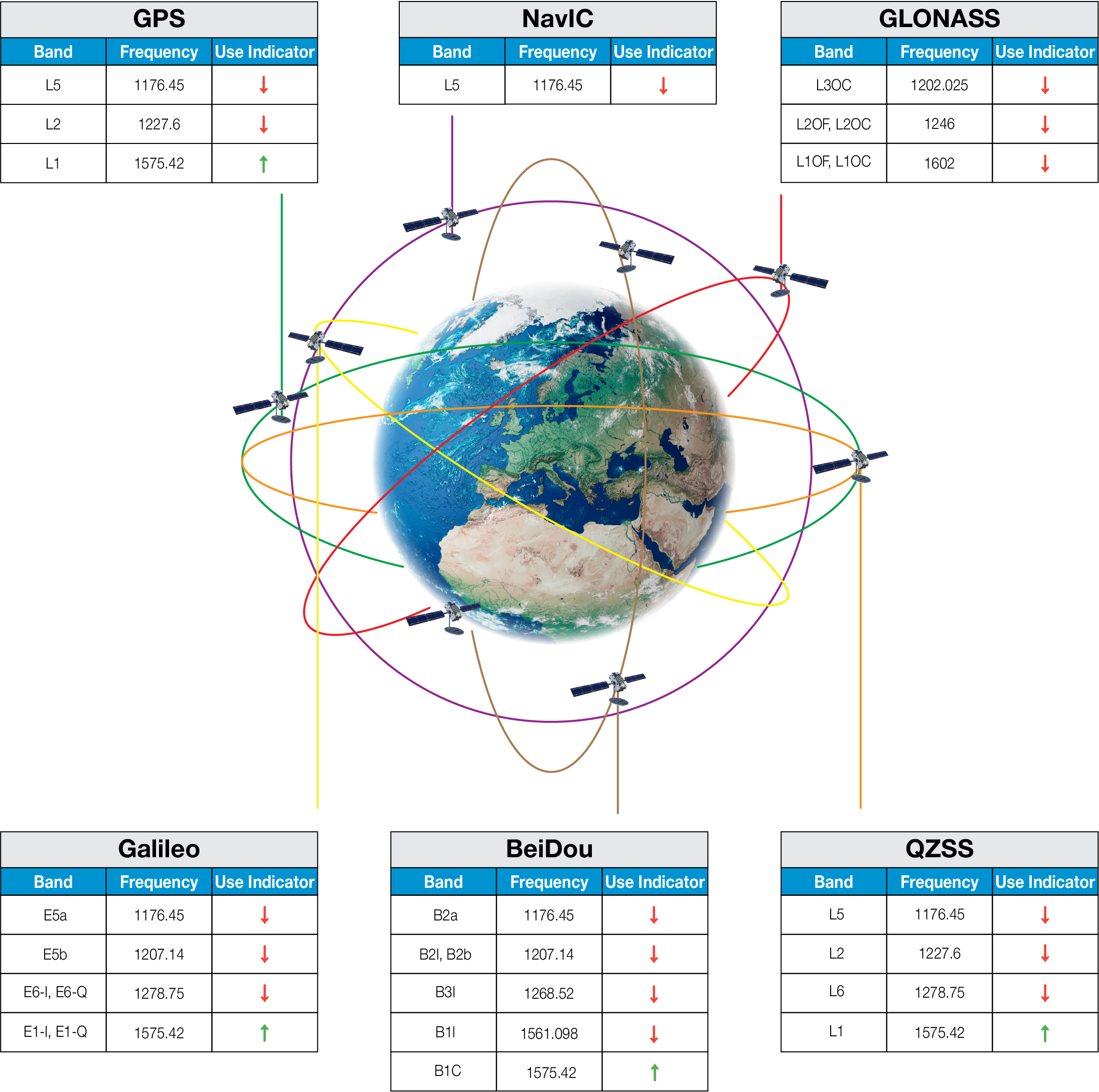
| ↑ Suitable band | □ Adequate band in good signal conditions | ↓ Likely to be unsuitable |
¶ GNSS Standards Band Support
| Electrical Interface | Spherical RF Measurements | |||
|---|---|---|---|---|
| Centre Frequency (MHz) | VSWR | Return Loss (dB) | Average RHCP Gain (dBiC) | Peak RHCP Gain (dBiC) |
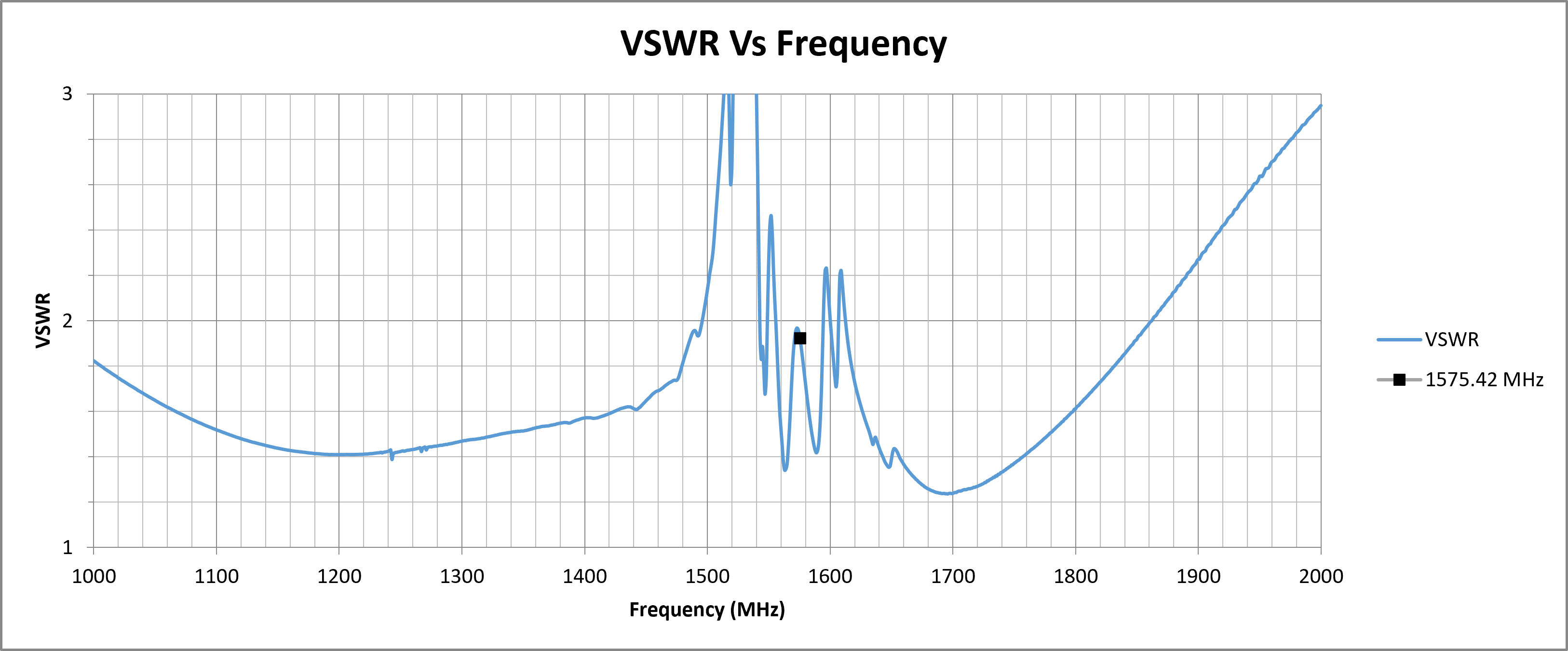
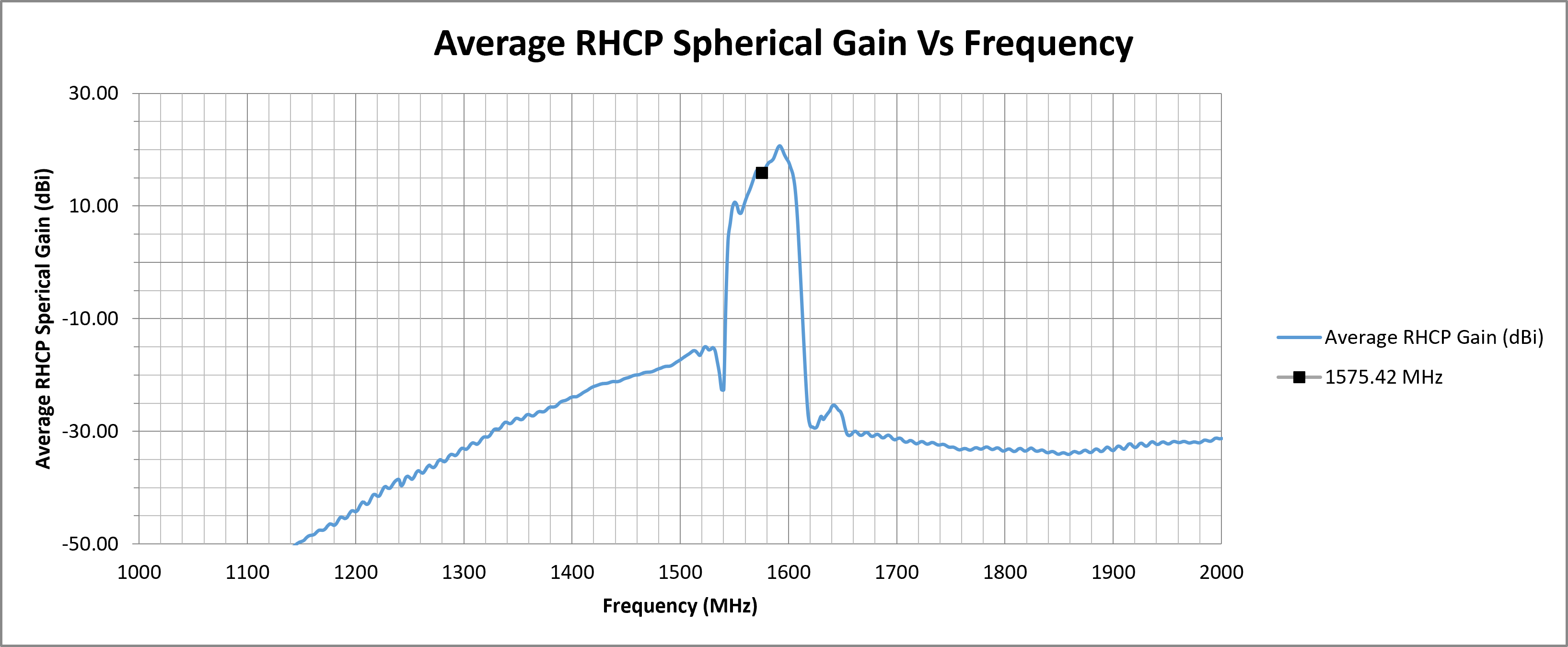
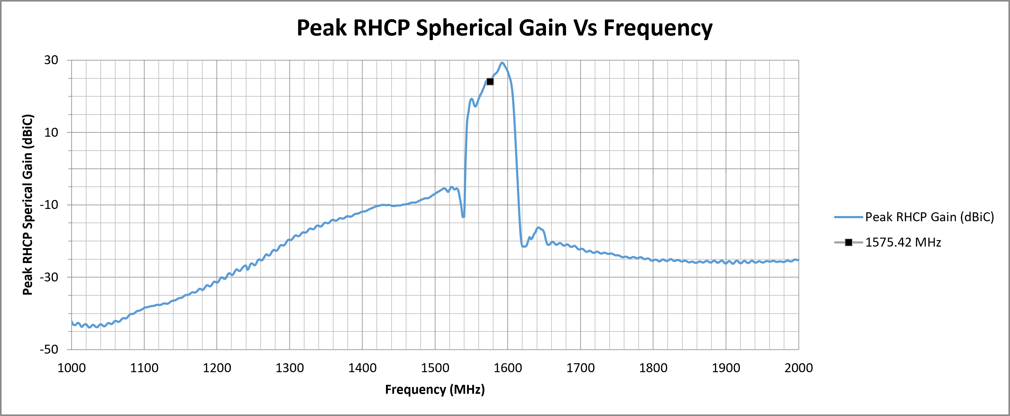
| 1575.42 (L1) | 1.9245 | -10.0040 | 15.91 | 24.15 |
| Top Hemisphere RF Measurements | Zenith RF Measurements | ||
|---|---|---|---|
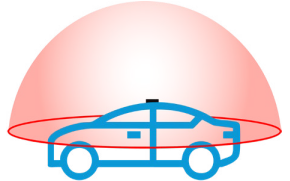
| Centre Frequency (MHz) | Average RHCP Gain (dBiC) | Peak RHCP Gain (dBiC) | RHCP Gain at Zenith (dBiC) |
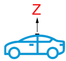
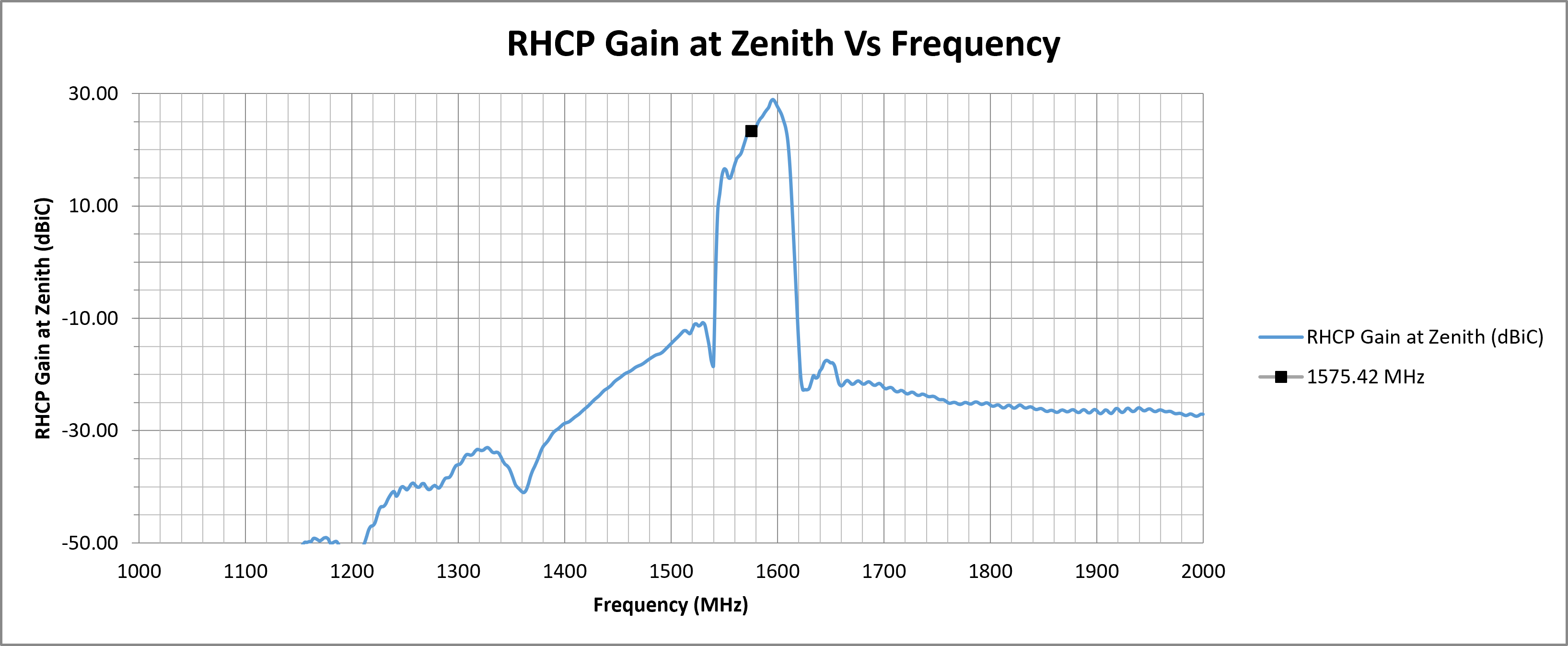
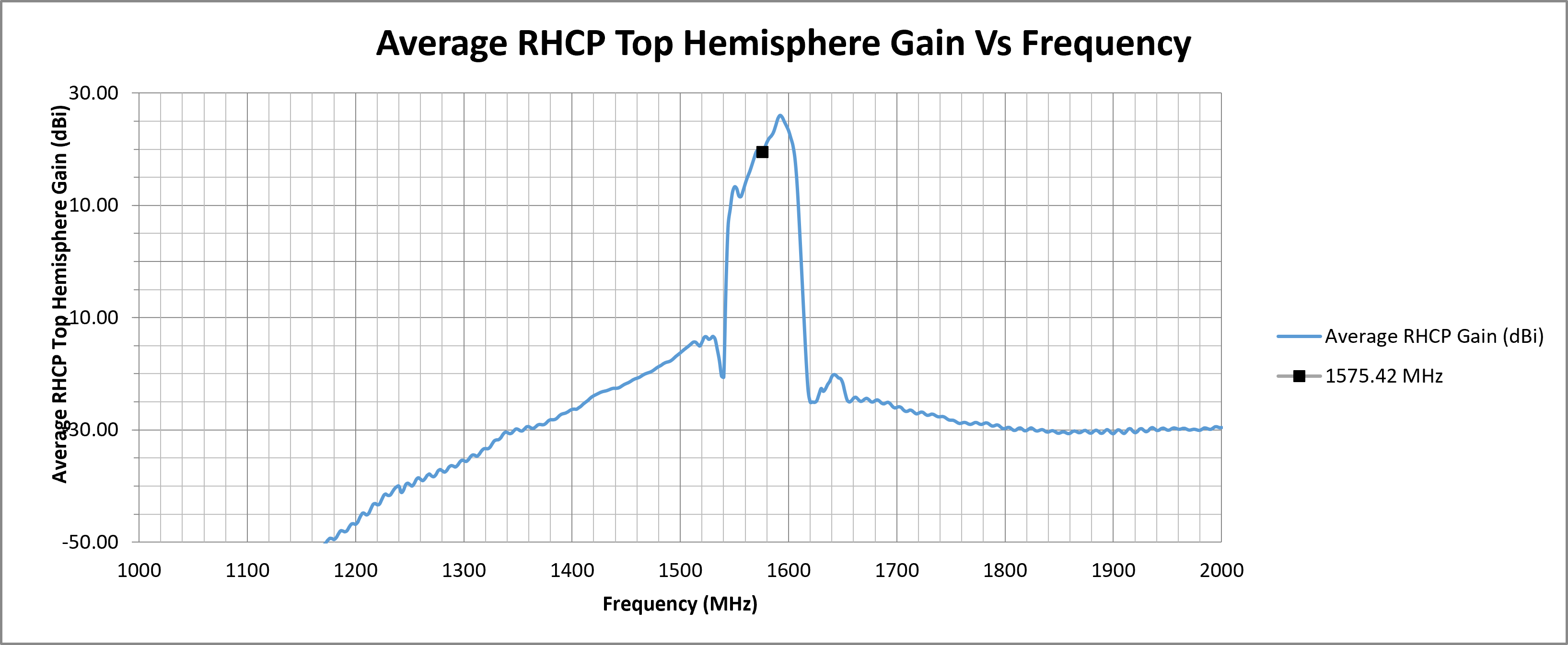
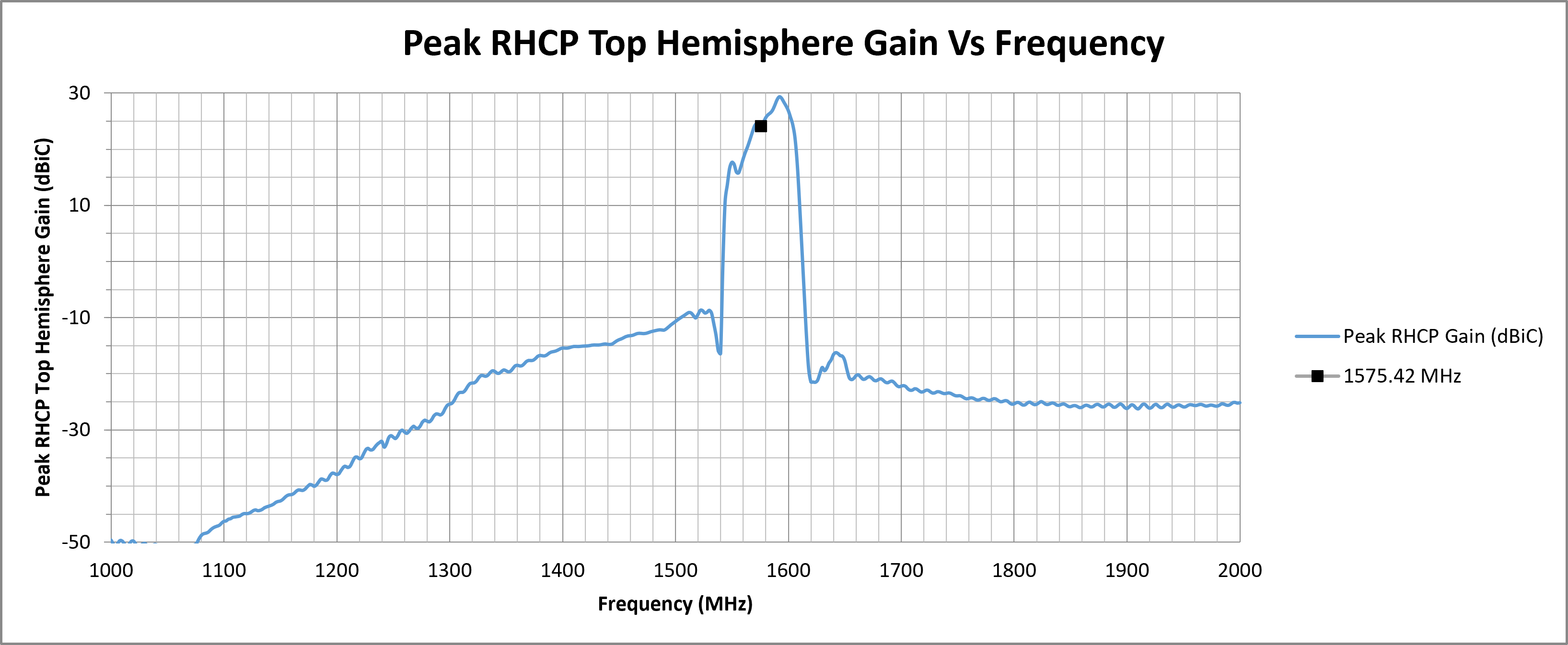
| 1575.42 (L1) | 19.56 | 24.15 | 23.36 |
¶ RF Matching Performance
This section illustrates the antenna's impedance matching characteristics across the operating frequency range using VSWR and Return Loss measurements.
¶ RF Zenith
¶ RF Top Hemisphere
¶ RF Spherical
The following graphs display the Average and Peak RHCP Gain across the entire spherical coverage of the antenna. These metrics provide a comprehensive view of the antenna’s ability to receive signals from satellites at all elevations and directions.
Consistently high gain across the sphere ensures strong and stable GNSS reception in a variety of operating conditions.

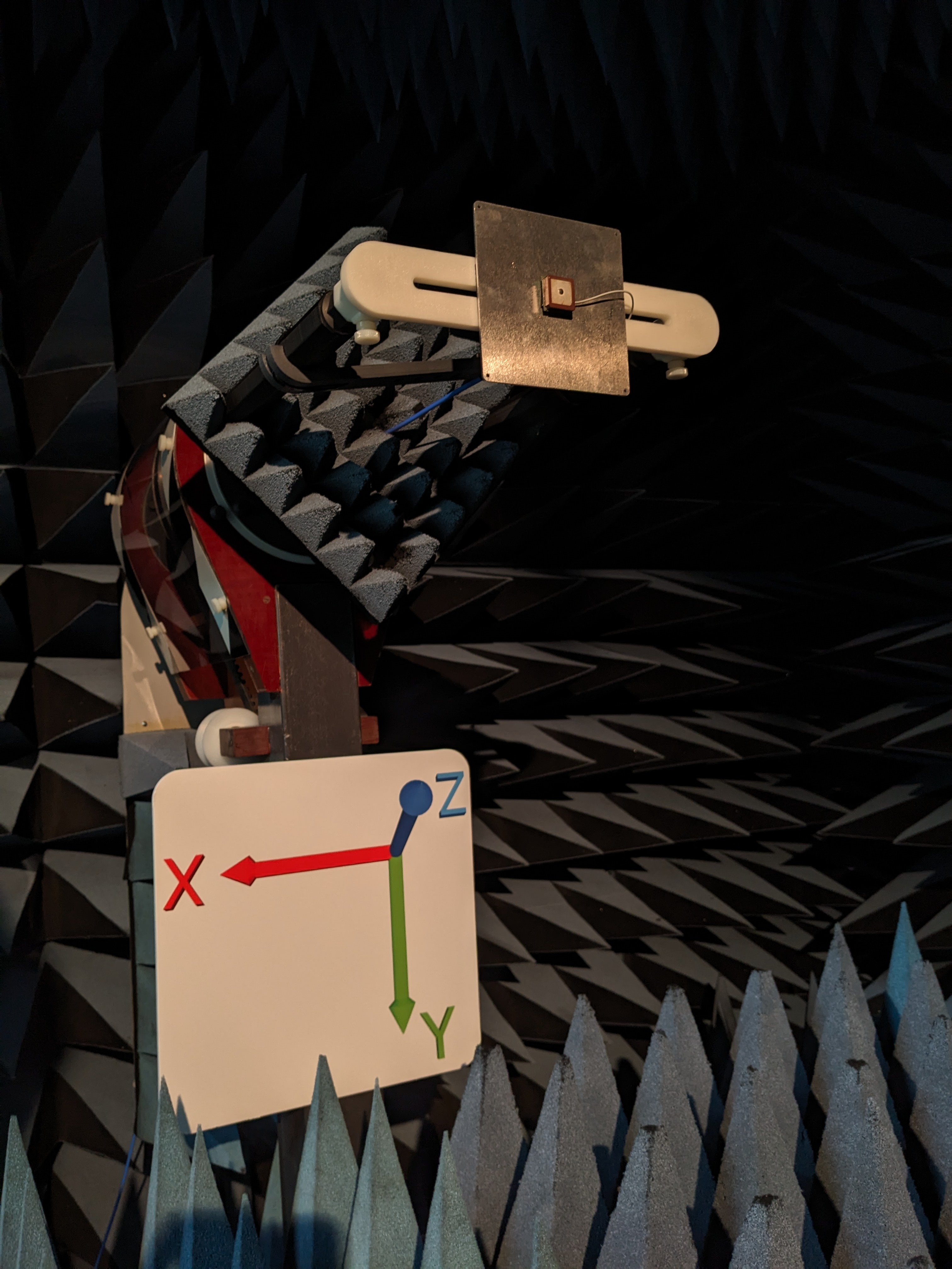
¶ Test Setup (on 100 x 100 mm Ground Plane)
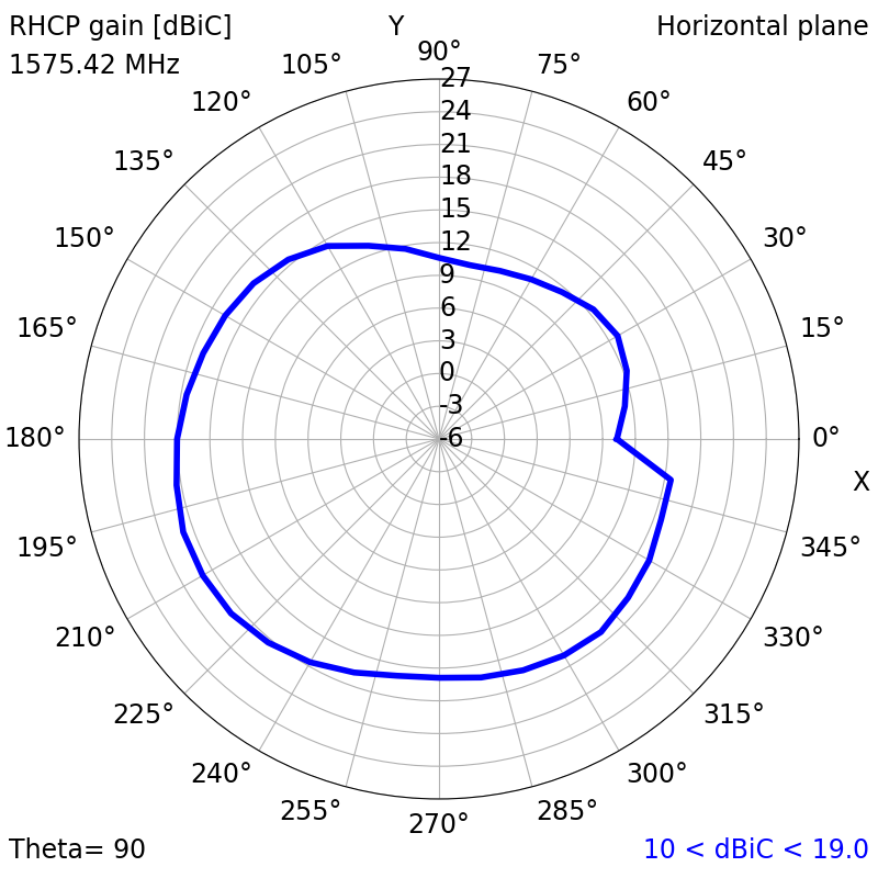
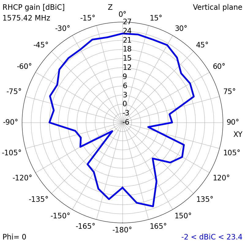
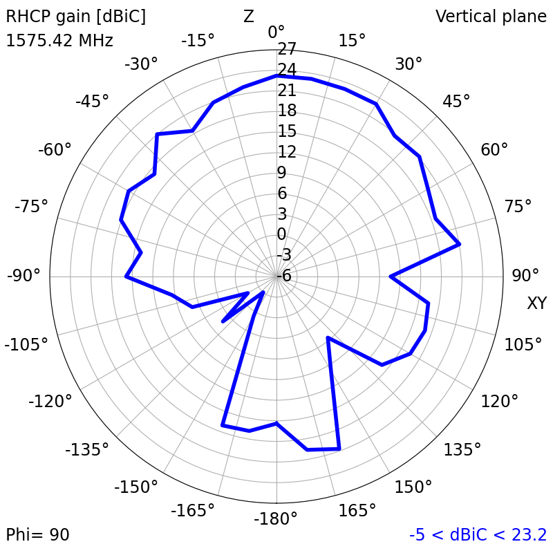
¶ 2D Radiation Plots
1575.42 MHz (L1)
|
|
|
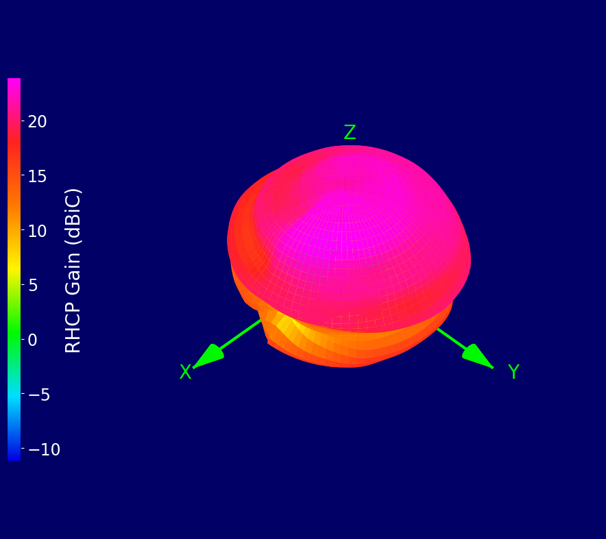
¶ 3D Radiation Plots
1575.42 MHz (L1)
¶ Ordering Details
| Part Number | Description |
|---|---|
| ECHO27/0.1M/IPEX/S/S/15 |
15 x 15 mm Active Ceramic Patch GPS L1 Embedded Antenna 100 mm Cable and U.FL/I-PEX Connector |