|
|
¶ General Description
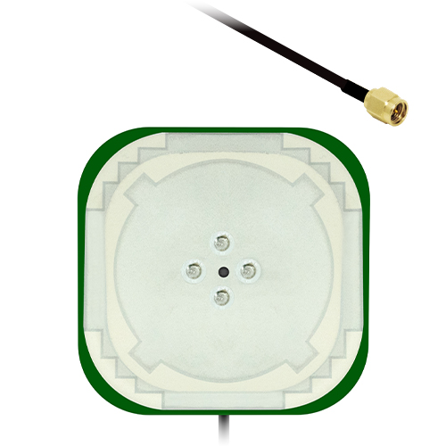
The Echo 50 is an active high-precision GNSS antenna designed for exceptional multi-constellation performance across all GPS, GLONASS, BeiDou, Galileo, NavIC, and QZSS bands. Integrated with a high-quality low noise amplifier, it delivers enhanced sensitivity and ensures reliable reception in challenging environments. With wideband support and low axial ratio, it enables sub-meter positional accuracy, and when paired with RTK corrections, centimetre-level precision is achievable.
Exceptional axial ratio, high gain, and pattern stability are achieved through the use of two orthogonal feeds in each patch, merged via a hybrid coupler. This ensures that the antenna delivers solid GNSS performance in challenging reception environments.
Supplied with a 0.1 m cable and SMAM, I-PEX MHF1, or MHF4 connector as standard, customised options are also available for high-volume orders.
¶ Key Features
- Covers all major GNSS bands worldwide, improving accuracy, reducing multipath errors and increasing satellite availability
- Active design with integrated LNA giving 23 ± 2 dB gain and ≤ 1.5 dB noise figure
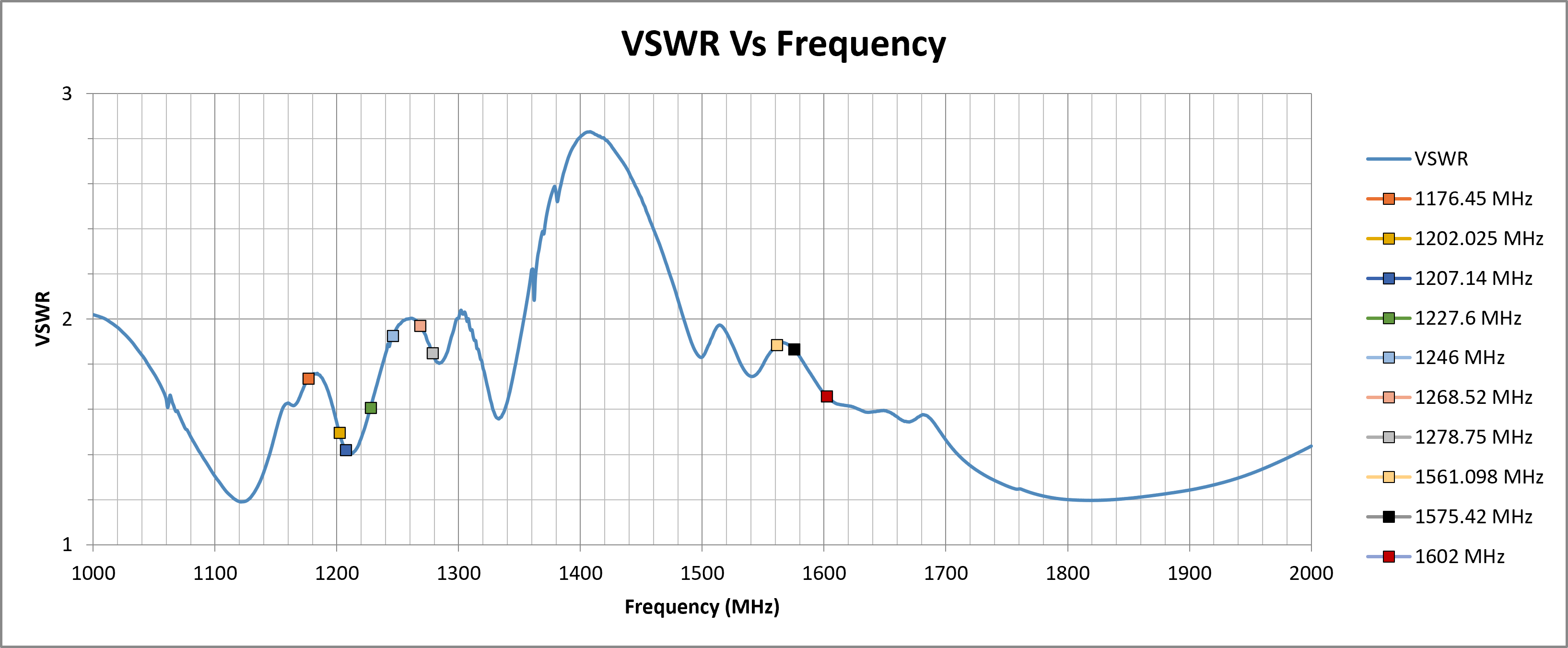
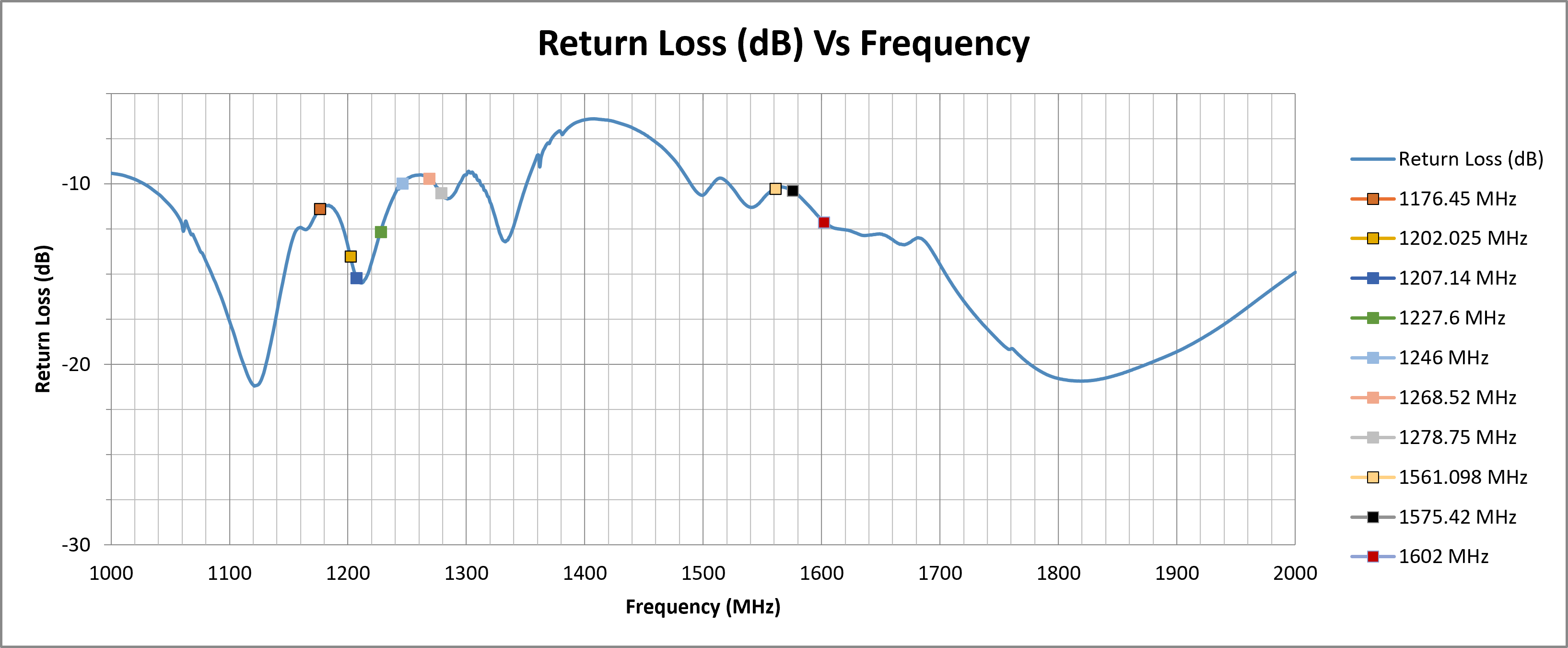
- Low VSWR across all measured bands (1.42–1.97), minimising signal loss
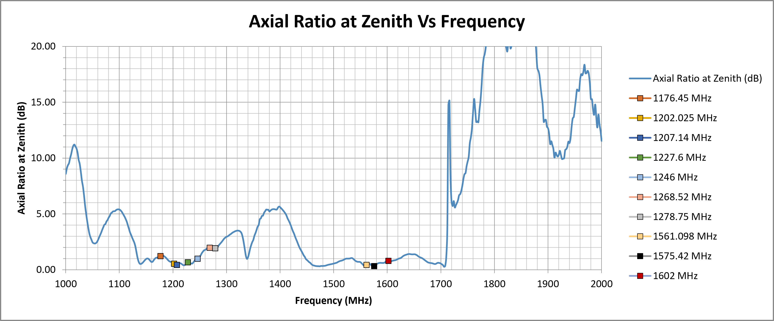
- Axial ratio as low as 0.34 dB at zenith for excellent circular polarisation
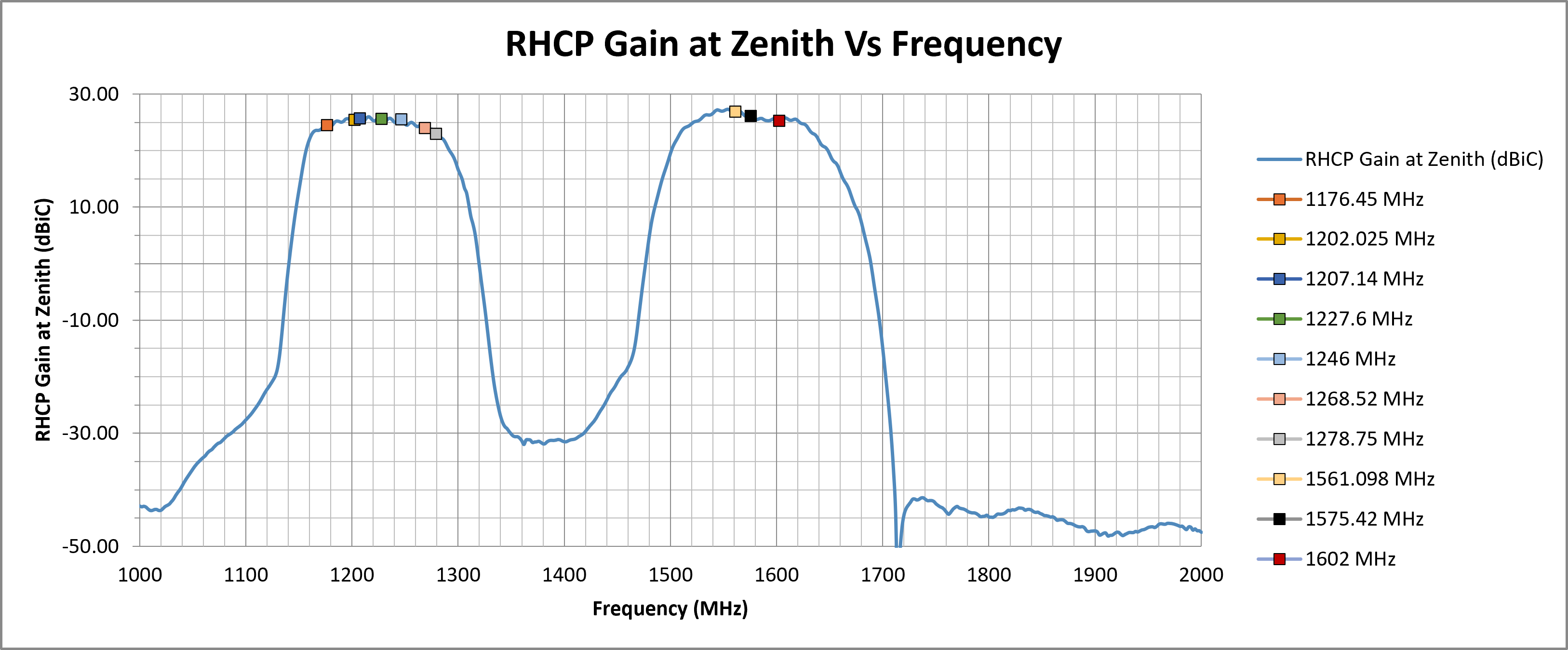
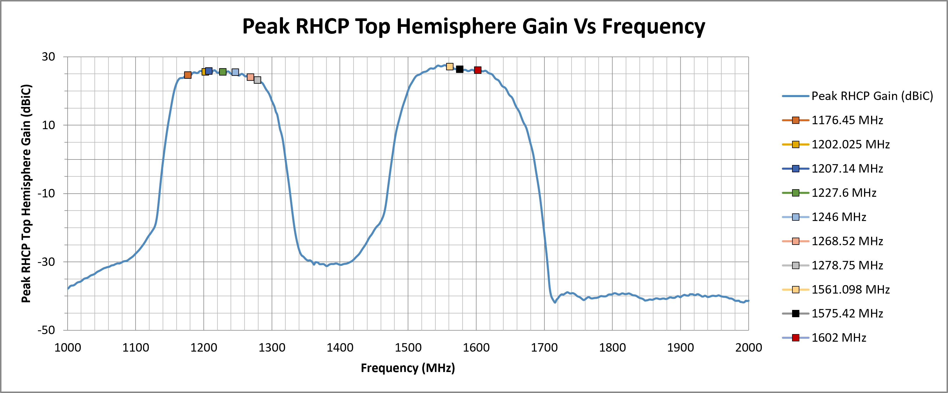
- Peak RHCP gain up to 27 dBiC for strong signal lock
- Compact embedded form for easy integration
¶ Typical Applications
- Land and hydrographic surveying
- Precision agriculture and machine guidance
- UAV photogrammetry and aerial mapping
- Autonomous vehicle navigation and control
- Geotechnical and structural monitoring
|
Multi-Band GNSS
1176–1602 MHz
|
Active Antenna
Integrated LNA
|
RHCP Gain
Up to 27 dBiC
|
Embedded
Installation
|
UAV Optimised
Ideal for Aerial Platforms
|
¶ Electrical Specifications
| Impedance: | 50 Ohm |
| Polarisation: | RHCP |
| Frequency Range: | 1176.45 – 1602 MHz |
| Return Loss: | ≤ -9.71 dB |
| VSWR: | ≤ 2 |
| Required Ground Plane: | Free space |
| Peak RHCP Gain (Top Hemisphere): |
27.19 dBiC |
| Noise Figure: | ≤ 1.5 dB |
| Supply Voltage: | 3 – 12 V DC (typ. 3.0 V) |
| Current Consumption: | ≤ 50 mA |
¶ Environmental Specifications
| Operating Temperature Range: | -40 °C to +85 °C |
| Storage Temperature Range: | -40 °C to +85 °C |
| Humidity: | Up to 95% RH |
¶ Mechanical Specifications
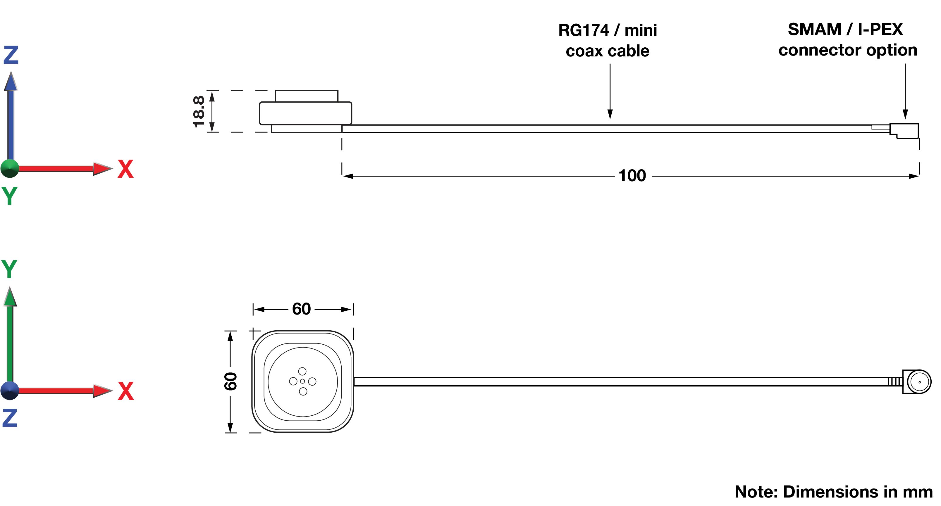
| Dimensions: | 60 × 60 × 18.8 mm |
| Weight: | 52 g |
| Connector: | SMA Male / U.FL/I-PEX MHF1 / I-PEX MHF4 (other custom options available for high-volume orders) |
| Cable: | RG174 (for SMA variants) / OD 1.13 mini coax (for I-PEX connectors) |
| Mounting Method: | Embedded (magnetic & adhesive options available on request) |
¶ Spectrum Coverage*
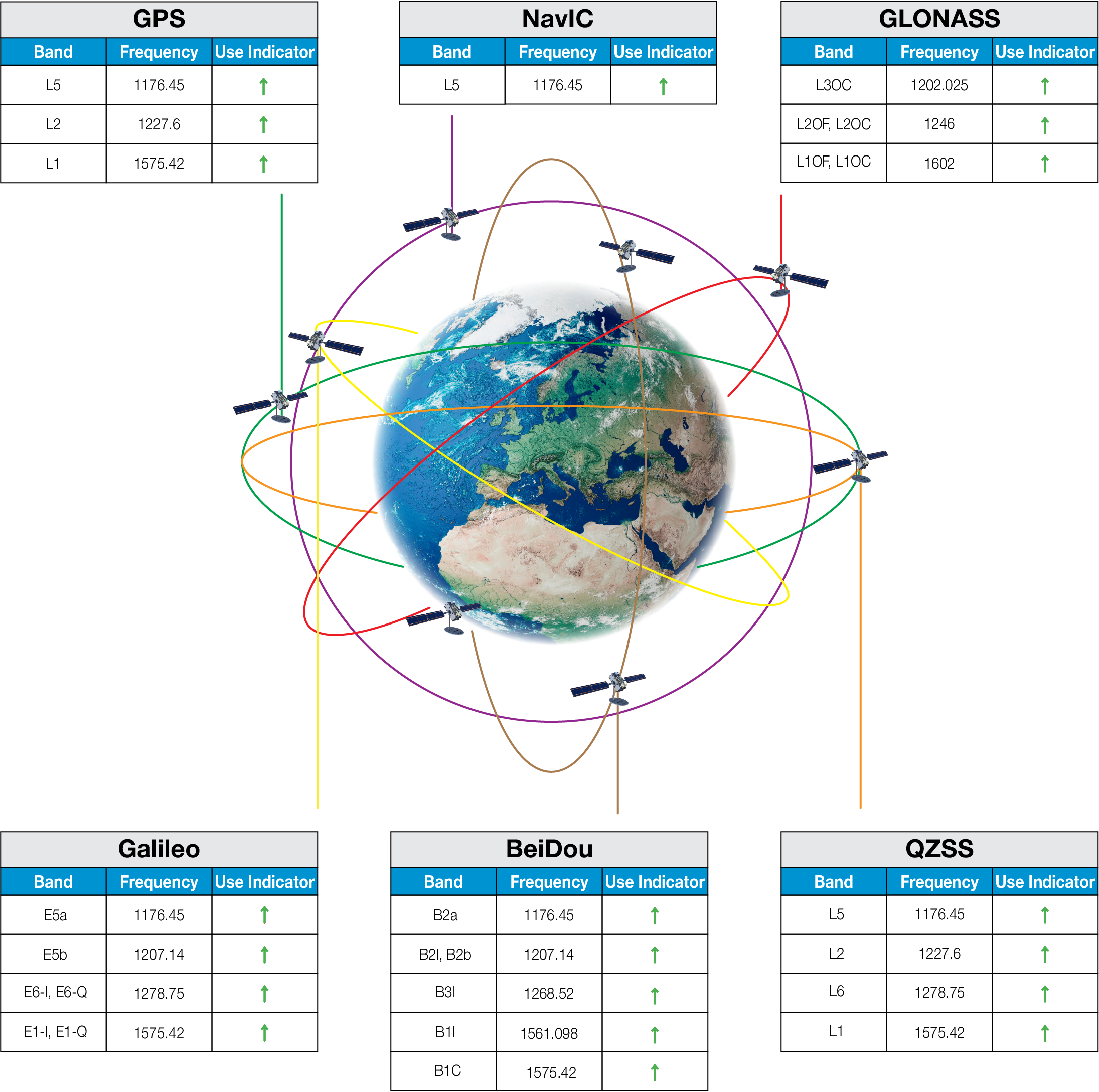
| ↑ Suitable band | □ Adequate band in good signal conditions | ↓ Likely to be unsuitable |
¶ GNSS Standards Band Support
| Electrical Interface | Spherical RF Measurements | |||||
|---|---|---|---|---|---|---|
| Centre Frequency (MHz) | VSWR | Return Loss (dB) | Average RHCP Gain (dBiC) | Peak RHCP Gain (dBiC) | Median Axial Ratio (dB) | Minimum Axial Ratio (dB) |
| 1176.45 (L5) | 1.7368 | -11.3978 | 18.15 | 24.72 | 3.58 | 0.10 |
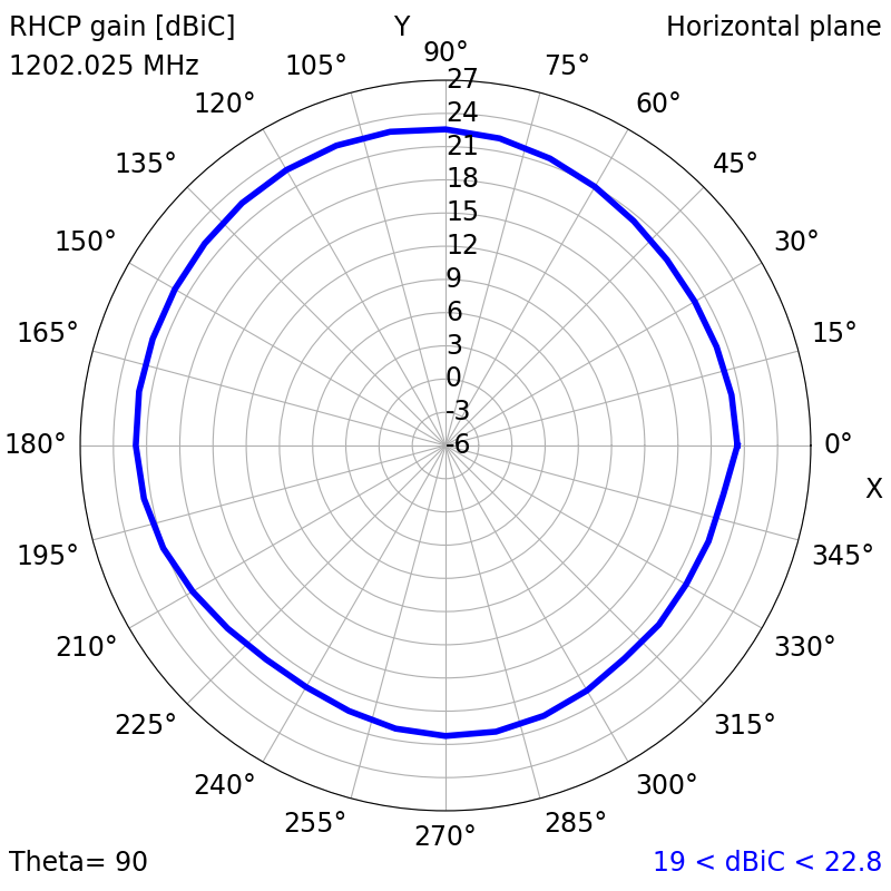
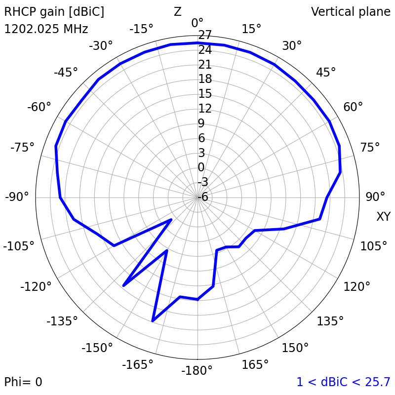
| 1202.025 (L3OC) | 1.4968 | -14.0248 | 18.89 | 25.68 | 2.54 | 0.02 |
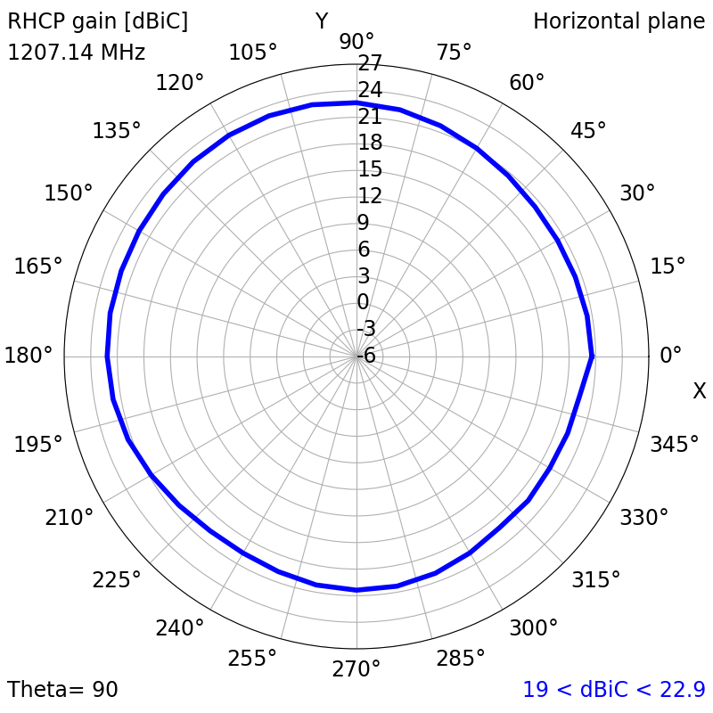
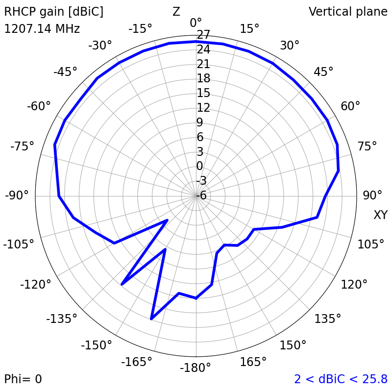
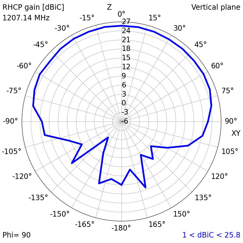
| 1207.14 (E5B) | 1.4203 | -15.2060 | 18.99 | 25.86 | 2.68 | 0.06 |
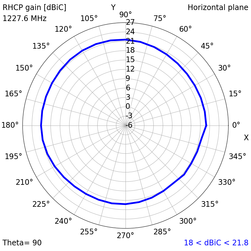
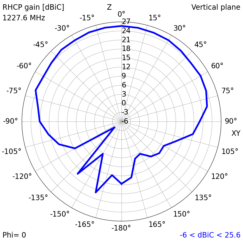
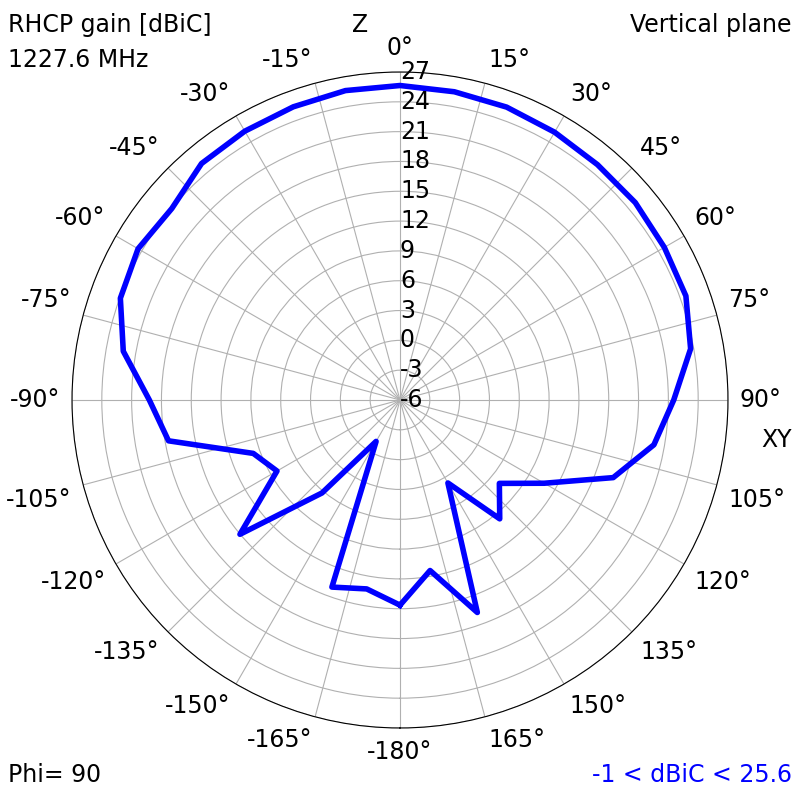
| 1227.6 (L2) | 1.6072 | -12.6584 | 18.45 | 25.64 | 3.14 | 0.08 |
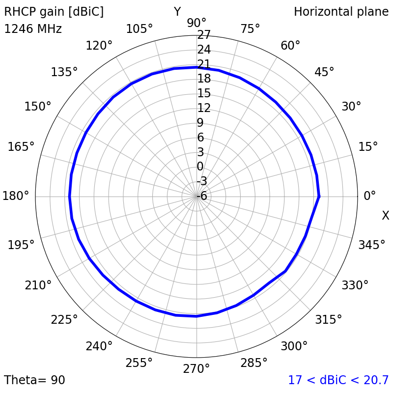
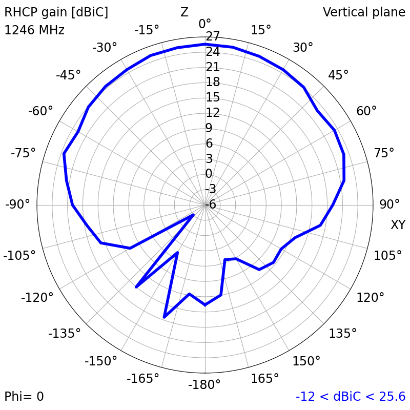
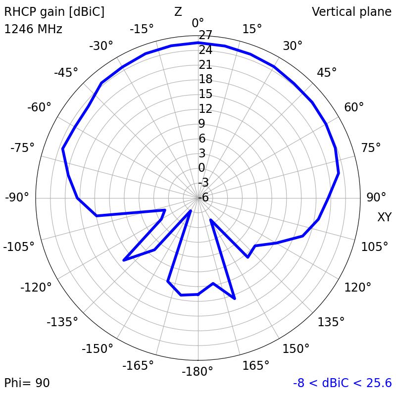
| 1246 (L20F/C) | 1.9272 | -9.9856 | 17.80 | 25.57 | 3.87 | 0.27 |
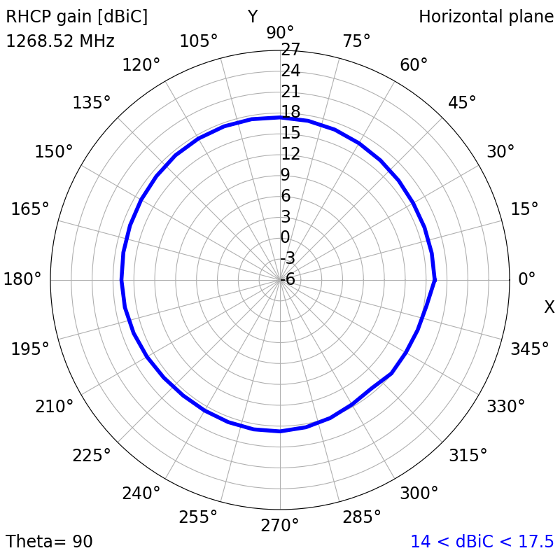
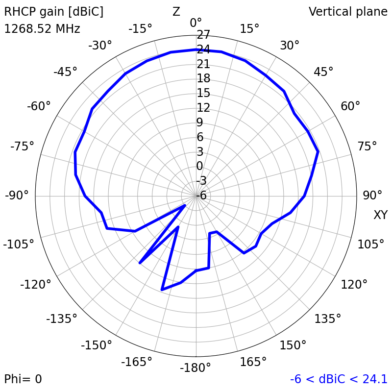
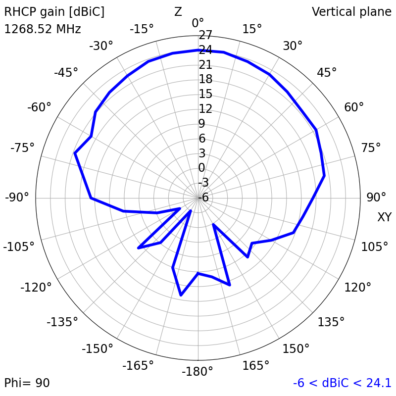
| 1268.52 (B3I) | 1.9718 | -9.7088 | 15.41 | 24.10 | 4.72 | 0.16 |
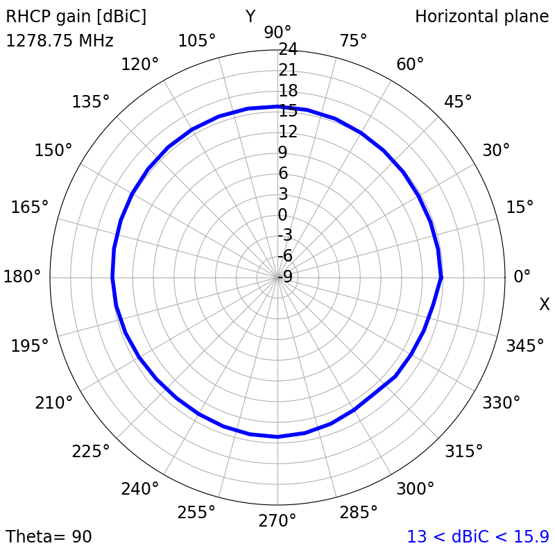
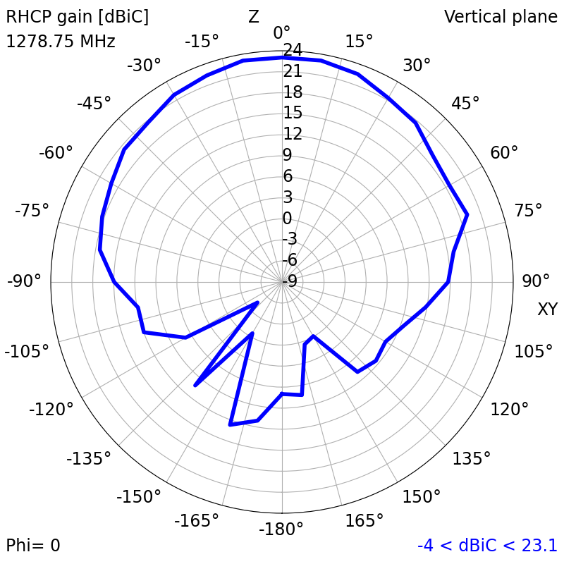
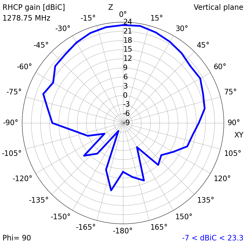
| 1278.75 (E6-I/Q) | 1.8501 | -10.5077 | 13.88 | 23.25 | 4.83 | 0.14 |
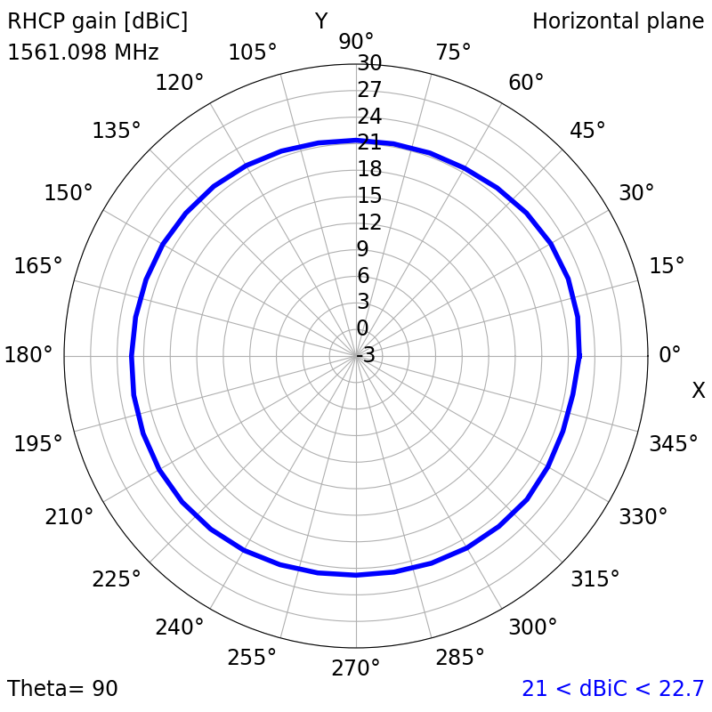
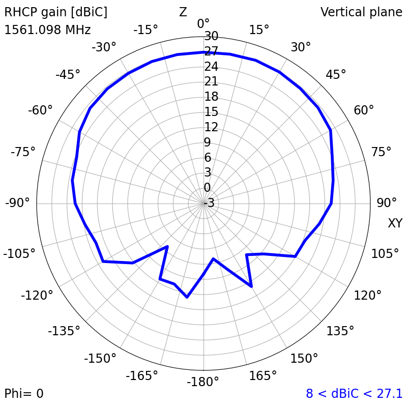
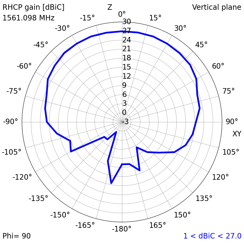
| 1561.098 (B1I) | 1.8853 | -10.2618 | 19.90 | 27.19 | 3.17 | 0.15 |
| 1575.42 (L1) | 1.8675 | -10.3847 | 18.45 | 26.40 | 2.64 | 0.03 |
| 1602 (L10F/C) | 1.6583 | -12.1233 | 17.97 | 26.12 | 1.74 | 0.07 |
| Top Hemisphere RF Measurements | Zenith RF Measurements | |||||
|---|---|---|---|---|---|---|
| Centre Frequency (MHz) | Average RHCP Gain (dBiC) | Peak RHCP Gain (dBiC) | Median Axial Ratio (dB) | Minimum Axial Ratio (dB) | RHCP Gain at Zenith (dBiC) | Axial Ratio at Zenith (dB) |
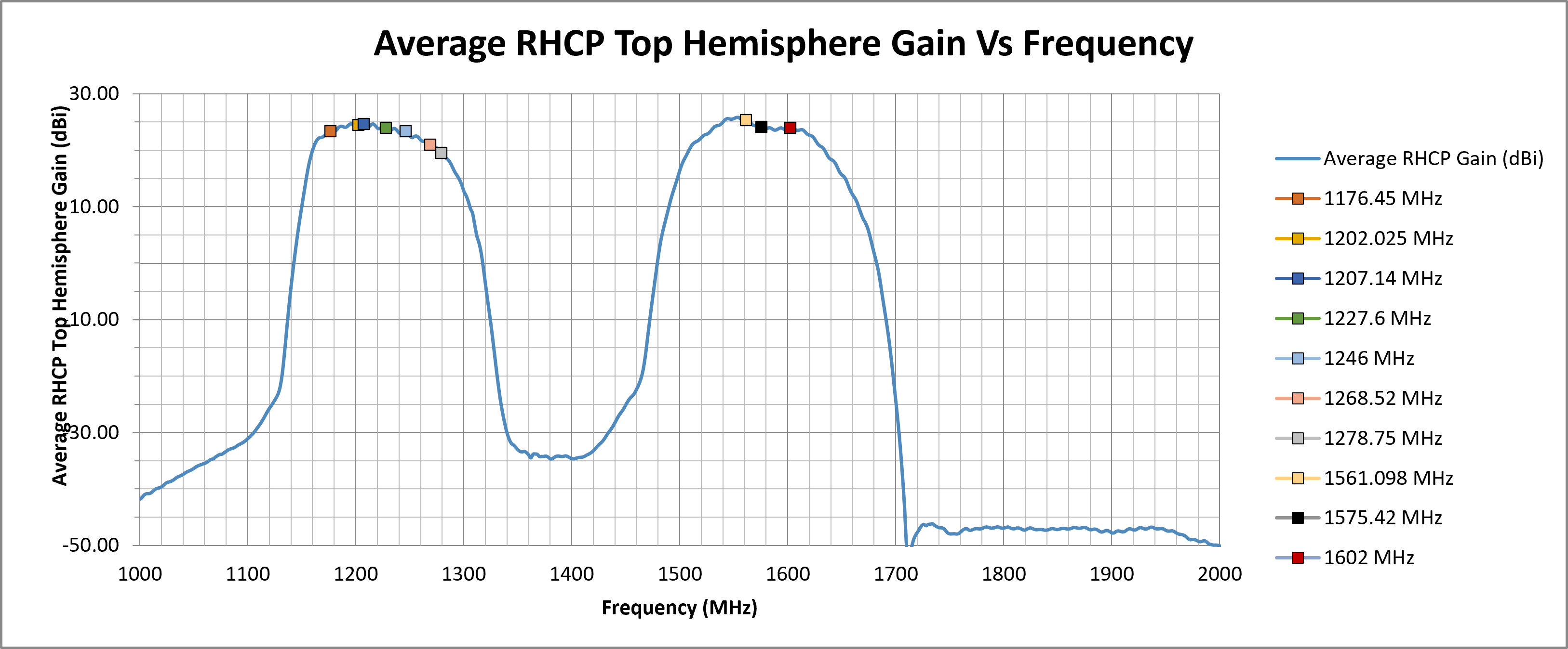
| 1176.45 (L5) | 23.45 | 24.72 | 1.88 | 0.10 | 24.51 | 1.23 |
| 1202.025 (L3OC) | 24.53 | 25.68 | 1.14 | 0.02 | 25.51 | 0.55 |
| 1207.14 (E5B) | 24.67 | 25.86 | 1.19 | 0.06 | 25.72 | 0.45 |
| 1227.6 (L2) | 24.05 | 25.64 | 1.85 | 0.08 | 25.64 | 0.68 |
| 1246 (L20F/C) | 23.42 | 25.57 | 2.44 | 0.27 | 25.57 | 1.00 |
| 1268.52 (B3I) | 21.05 | 24.10 | 2.93 | 0.16 | 24.06 | 1.97 |
| 1278.75 (E6-I/Q) | 19.58 | 23.25 | 2.90 | 0.14 | 23.04 | 1.94 |
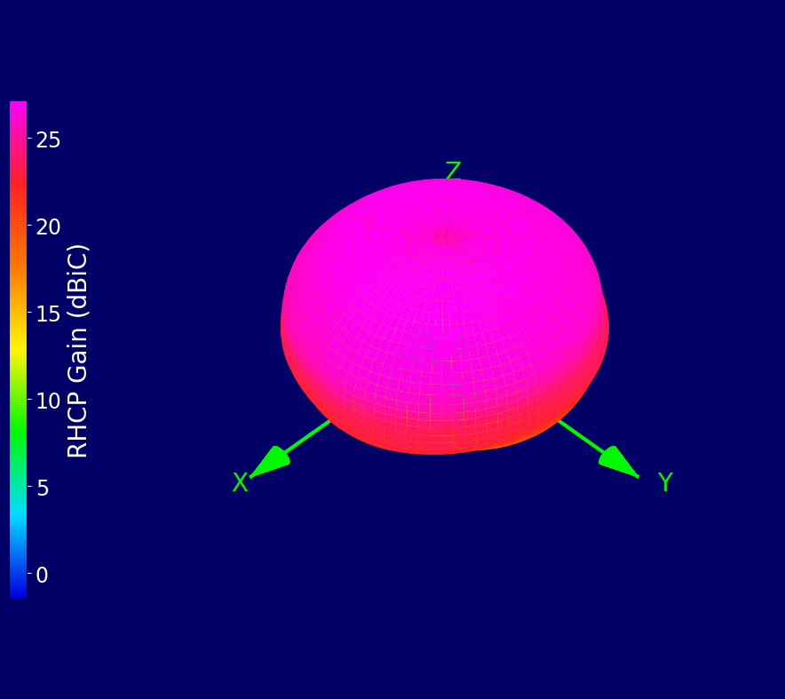
| 1561.098 (B1I) | 25.34 | 27.19 | 0.83 | 0.15 | 26.92 | 0.45 |
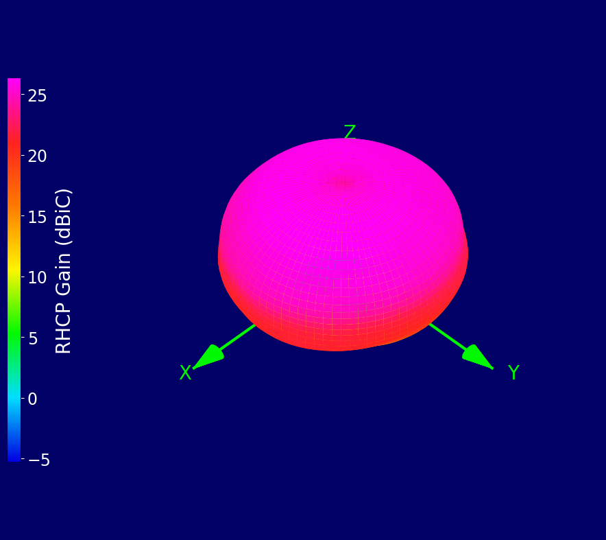
| 1575.42 (L1) | 24.21 | 26.40 | 0.92 | 0.03 | 26.14 | 0.34 |
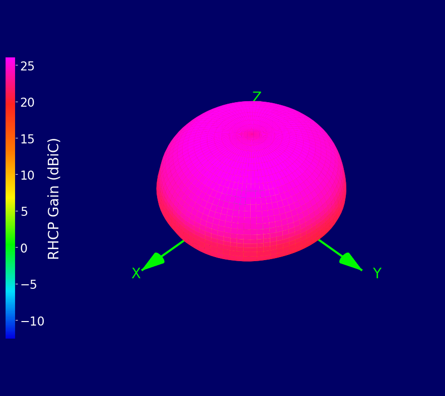
| 1602 (L10F/C) | 23.97 | 26.12 | 0.88 | 0.07 | 25.34 | 0.80 |
¶ RF Matching Performance
This section illustrates the antenna's impedance matching characteristics across the operating frequency range using VSWR and Return Loss measurements.
¶ RF Zenith
¶ RF Top Hemisphere
¶ RF Spherical
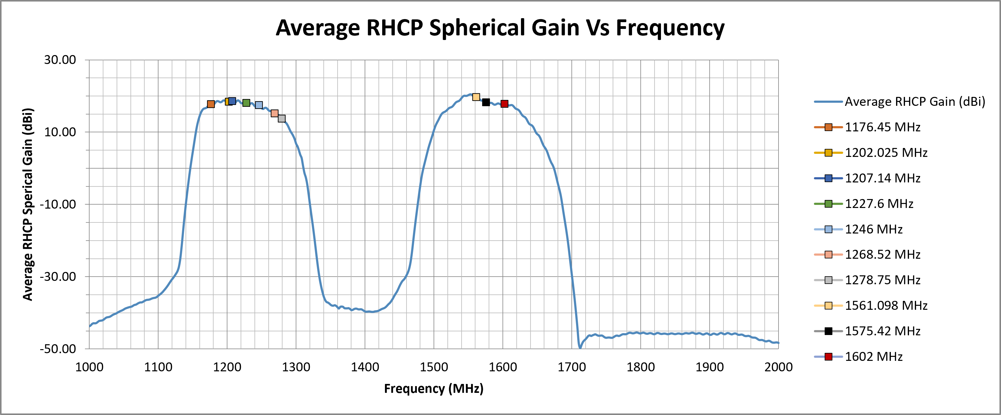
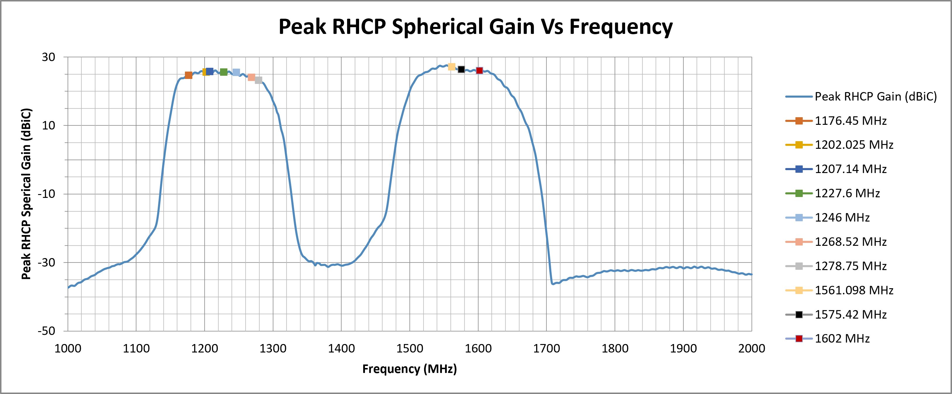
The following graphs display the Average and Peak RHCP Gain across the entire spherical coverage of the antenna. These metrics provide a comprehensive view of the antenna’s ability to receive signals from satellites at all elevations and directions.
Consistently high gain across the sphere ensures strong and stable GNSS reception in a variety of operating conditions.

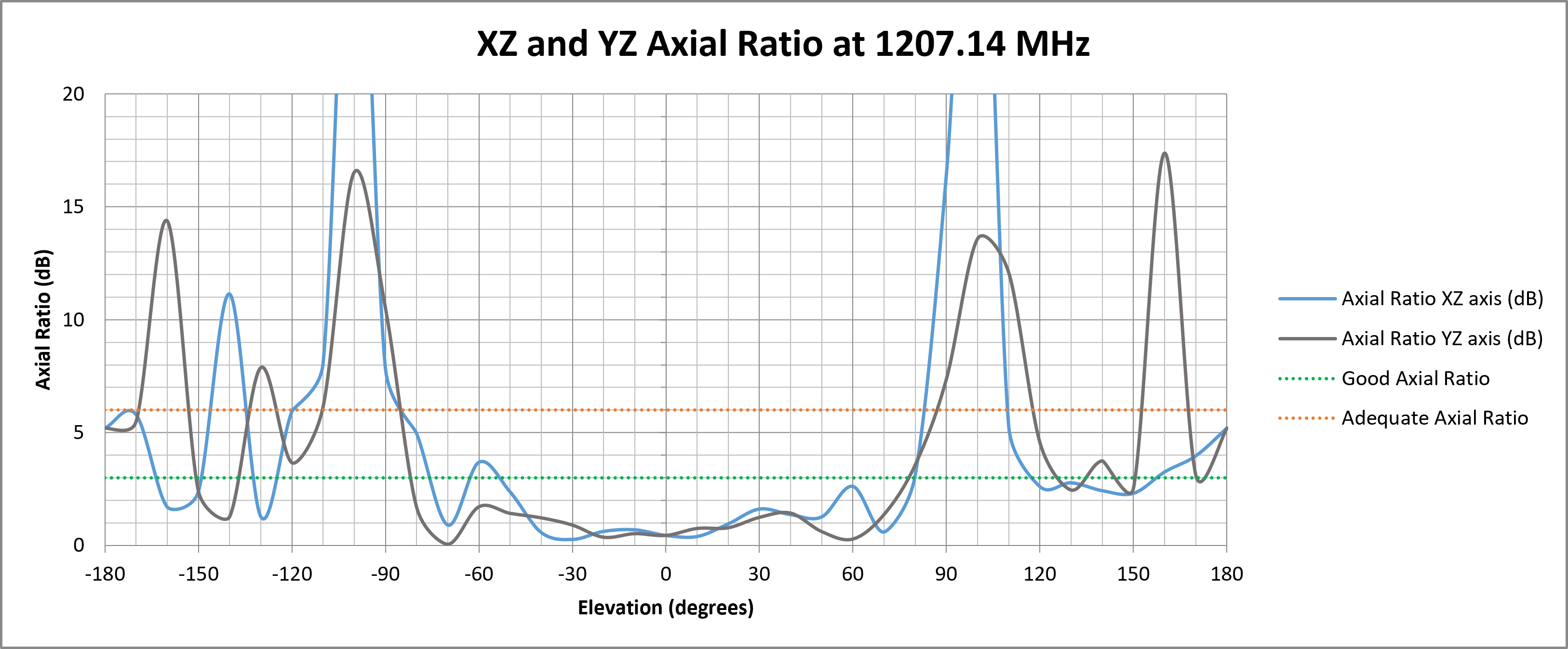
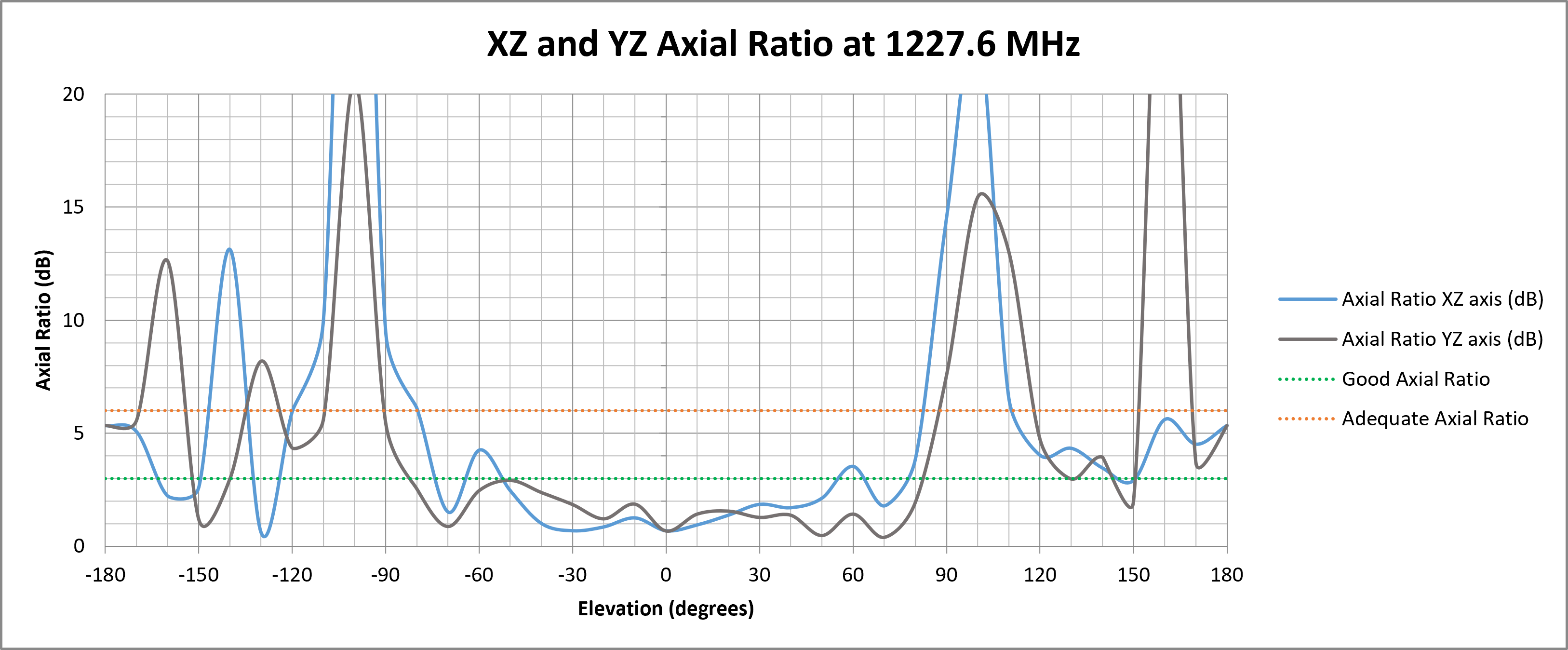
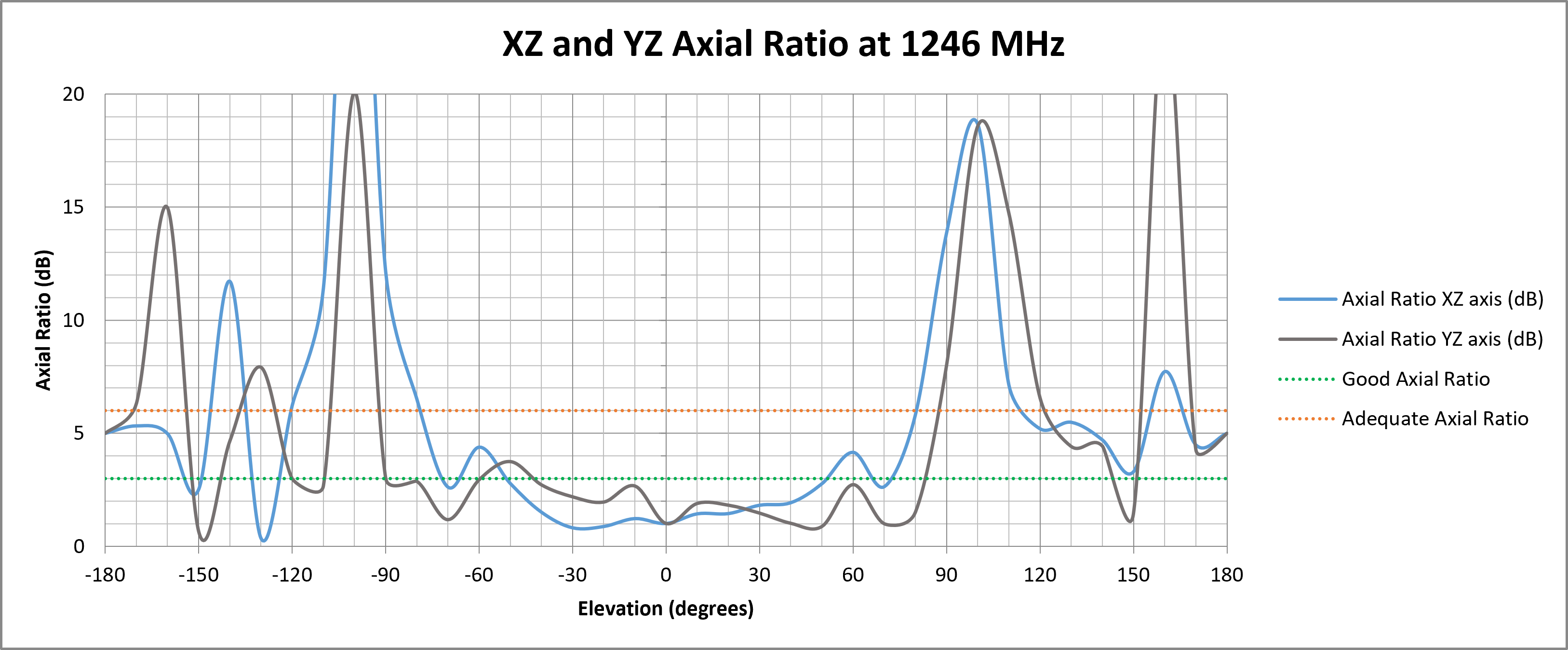
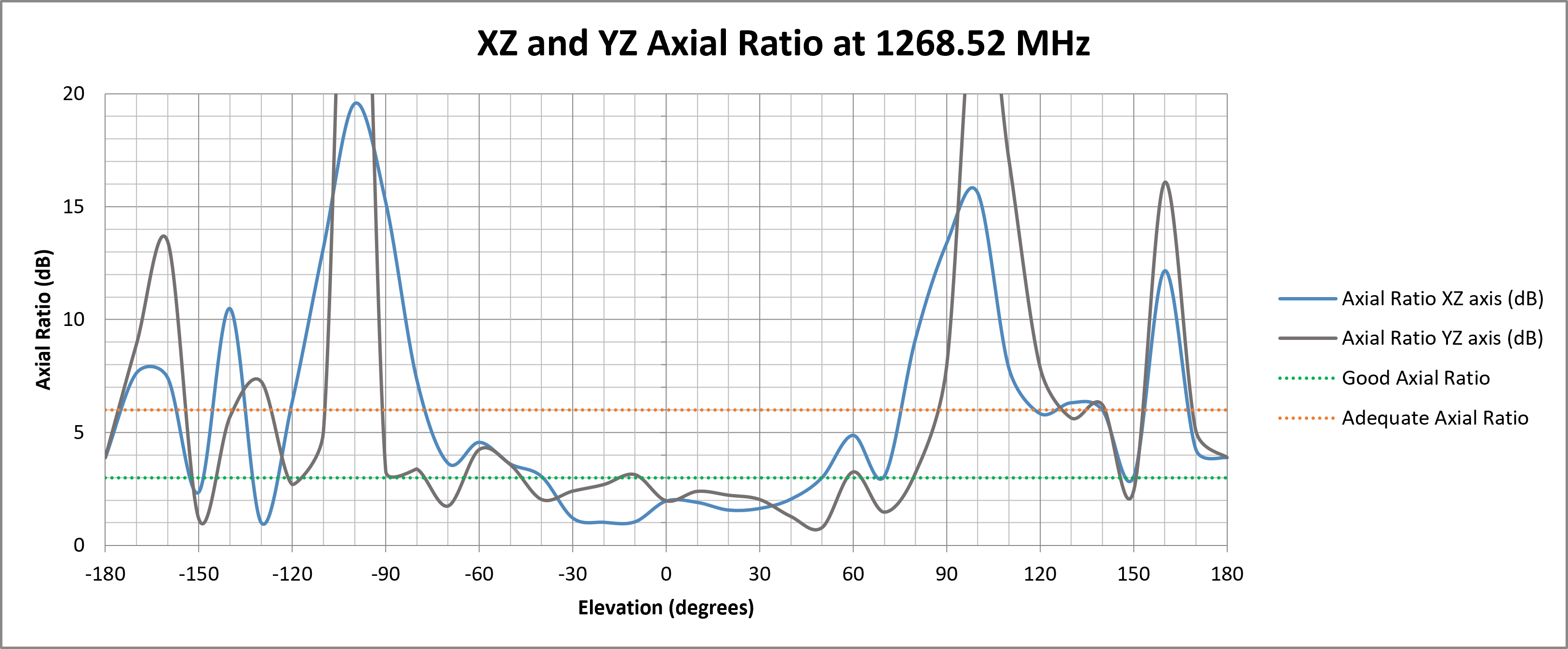
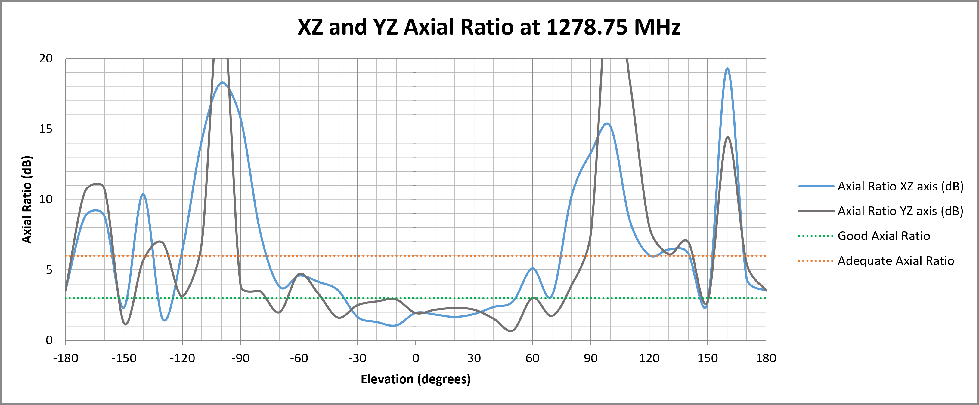
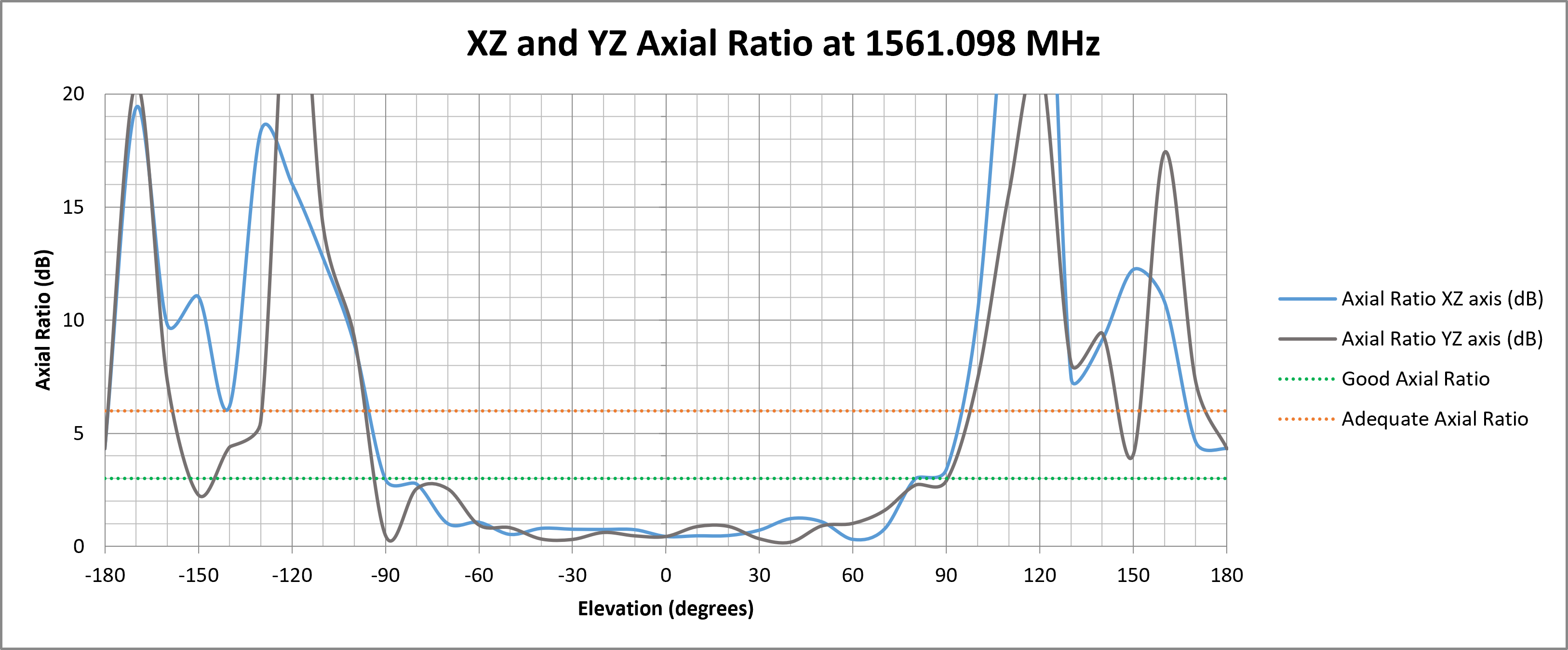
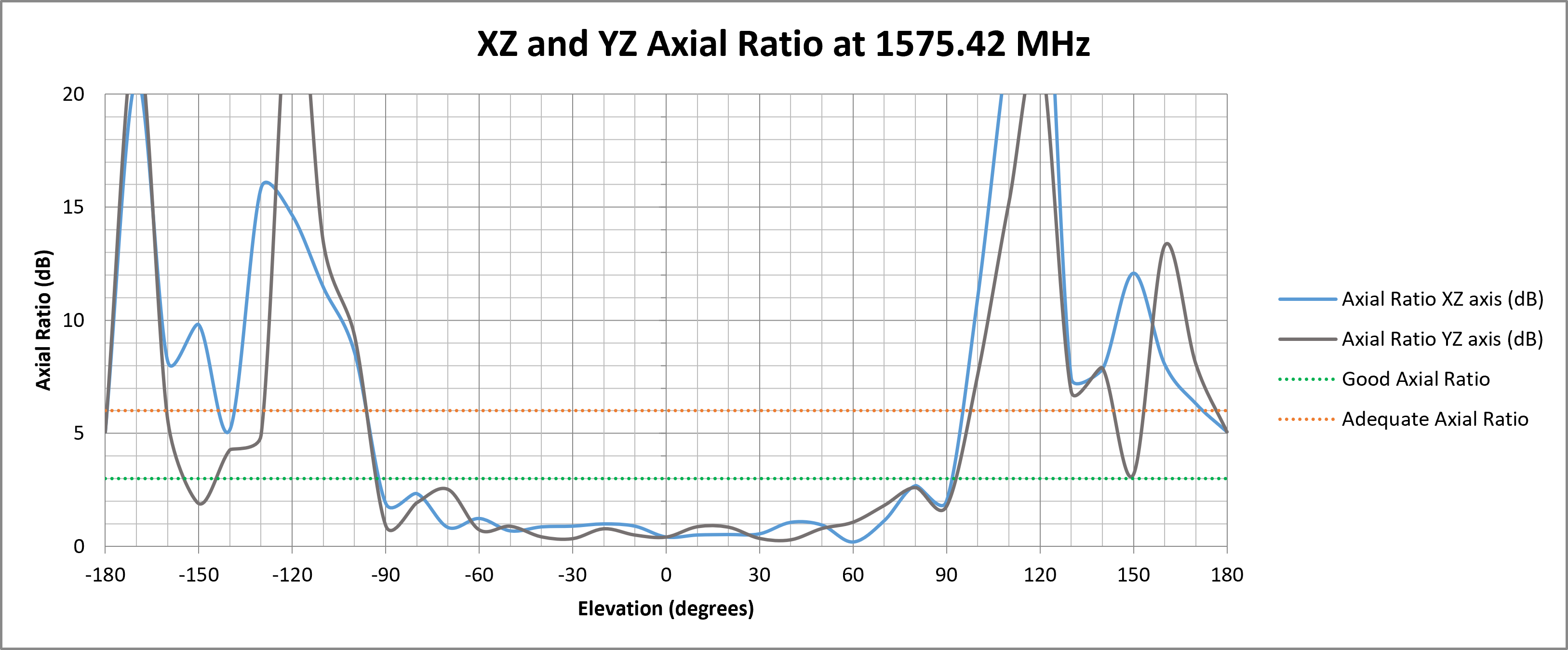
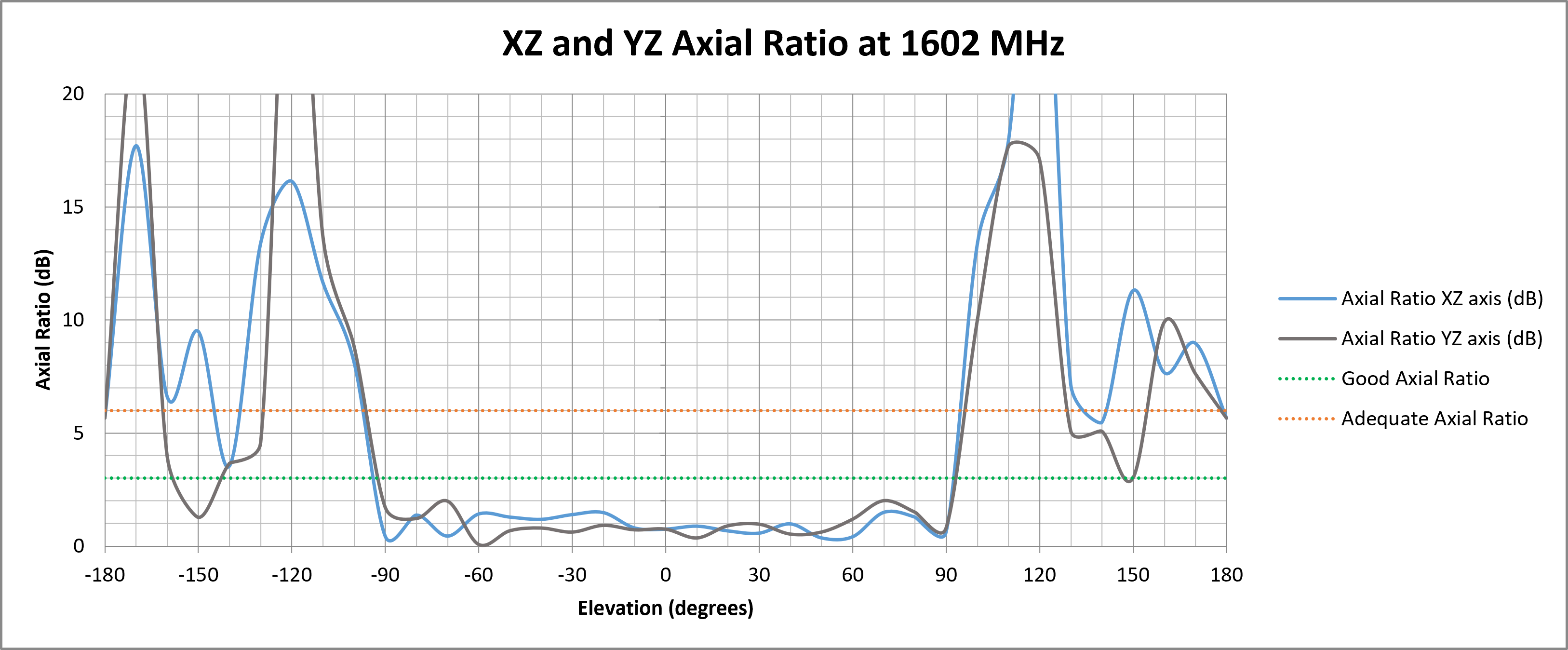
¶ ZX and YZ Plane Axial Ratio Plots (Zenith is at 0 degrees)
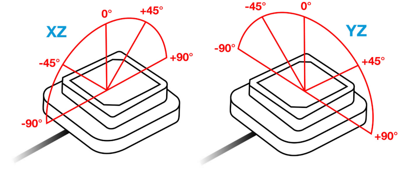
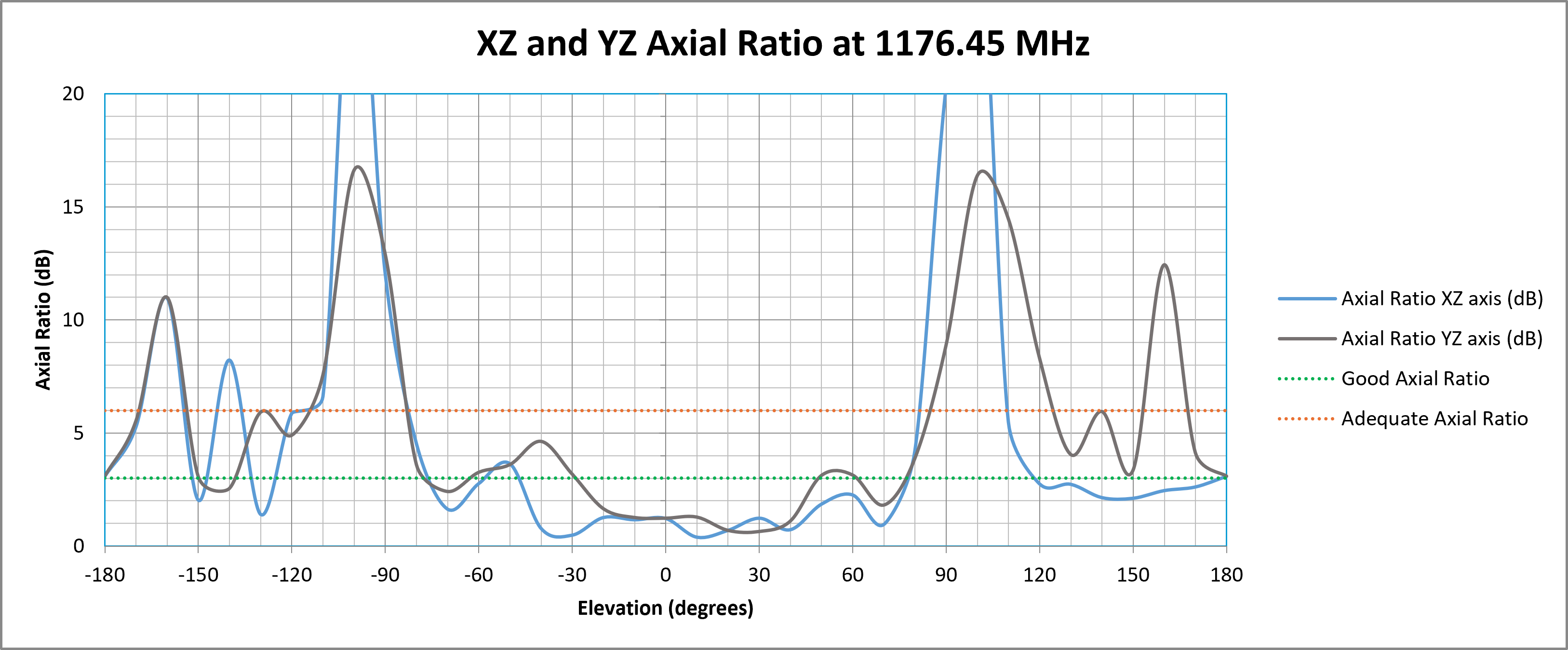
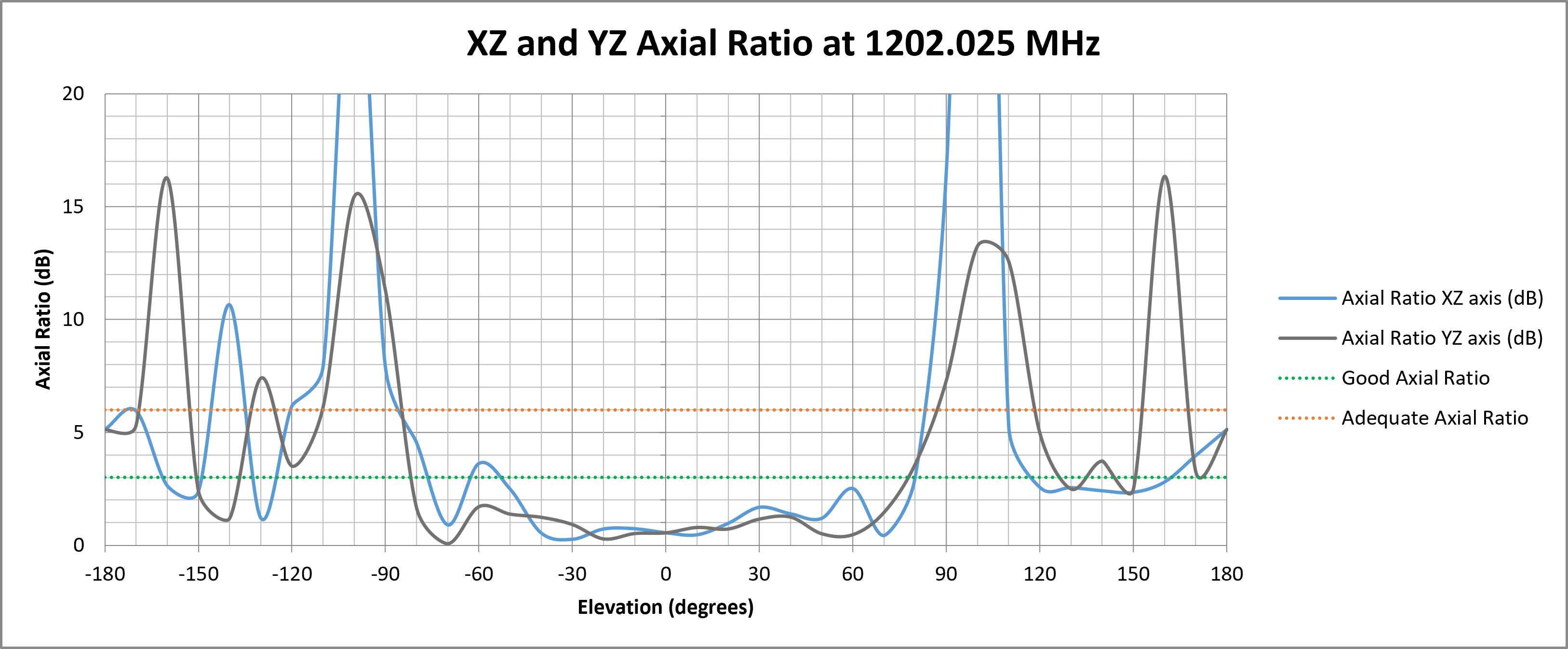
The following graphs show how well the antenna maintains circular polarisation at different elevation angles. A lower axial ratio ensures better GNSS signal reception, especially at low elevations, which is crucial for applications requiring strong performance in obstructed environments or wide-angle satellite visibility.
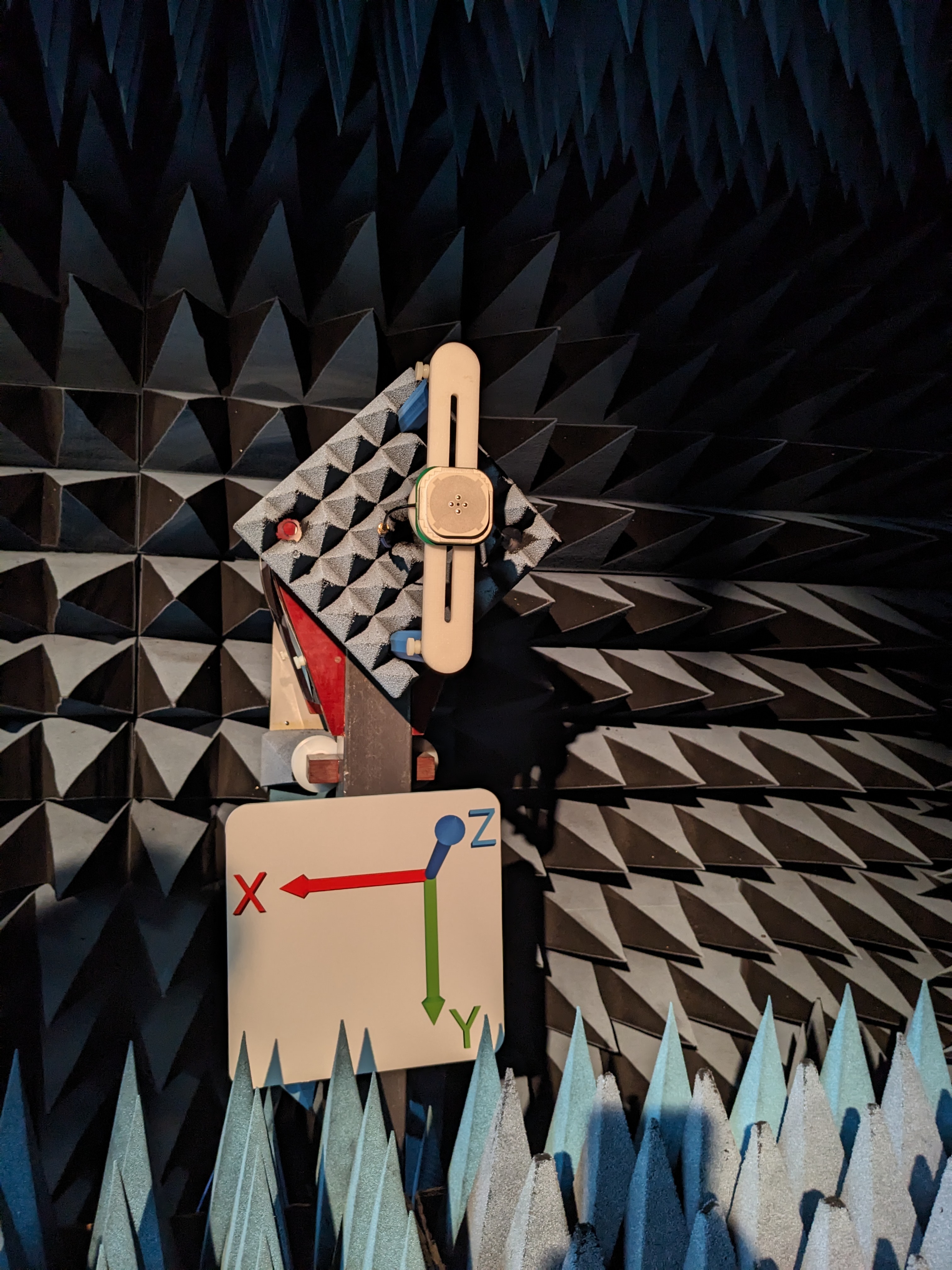
¶ Test Setup (in Free Space)
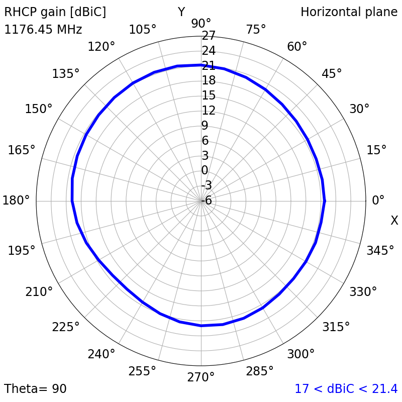
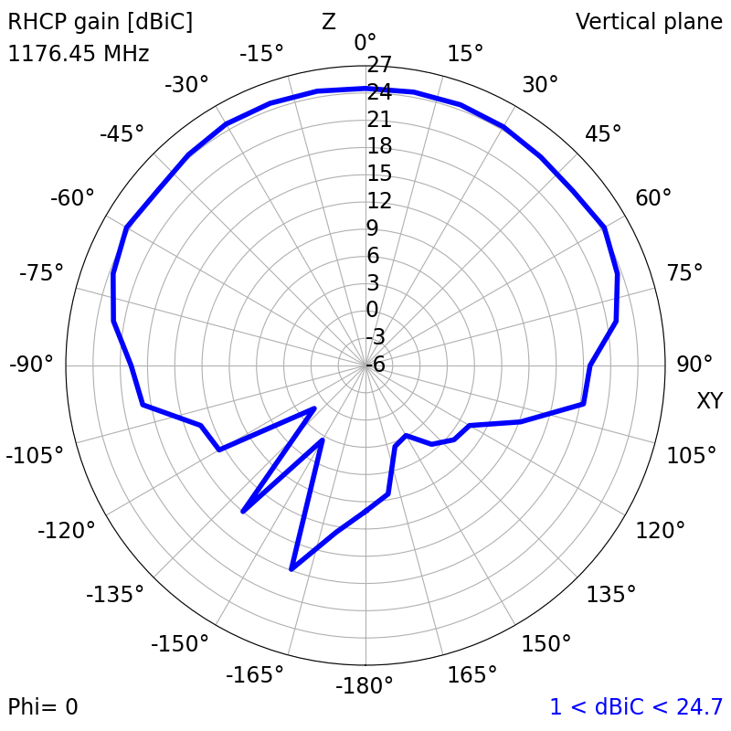
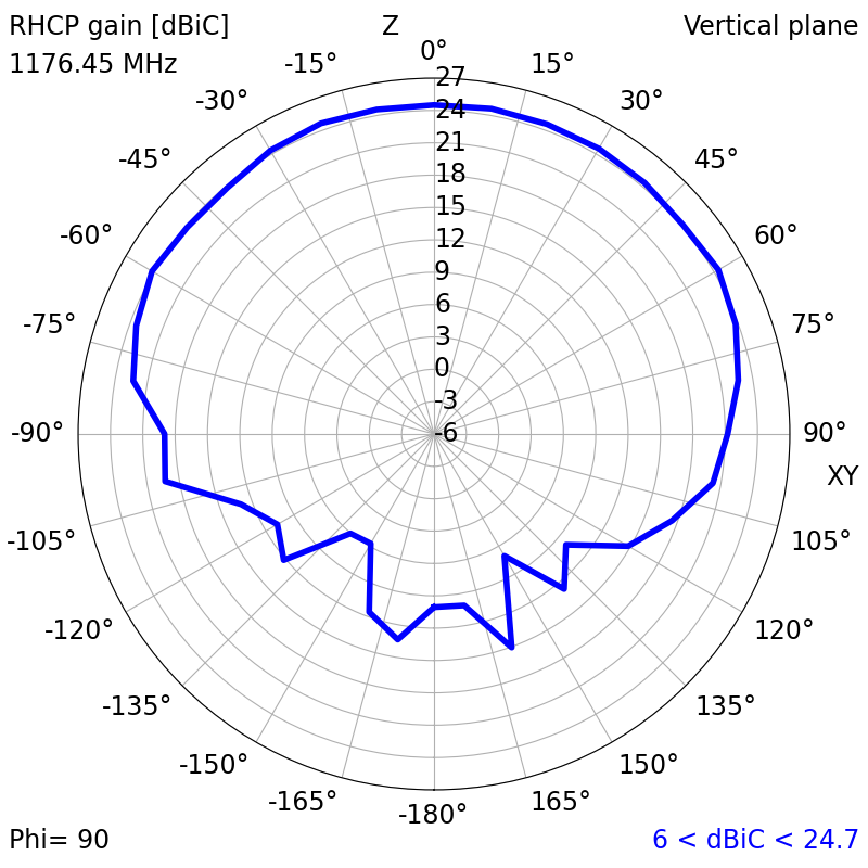
¶ 2D Radiation Plots
| 1176.45 MHz (L5) | ||
| XY | XZ | YZ |
|
|
|
| 1202.025 MHz (L30C) | ||
| XY | XZ | YZ |
|
|
|
| 1207.14 MHz (E5B) | ||
| XY | XZ | YZ |
|
|
|
| 1227.6 MHz (L2) | ||
| XY | XZ | YZ |
|
|
|
| 1246 MHz (L20F/C) | ||
| XY | XZ | YZ |
|
|
|
| 1268.52 MHz (B3I) | ||
| XY | XZ | YZ |
|
|
|
| 1278.75 MHz (E6-I/Q) | ||
| XY | XZ | YZ |
|
|
|
| 1561.098 MHz (B1I) | ||
| XY | XZ | YZ |
|
|
|
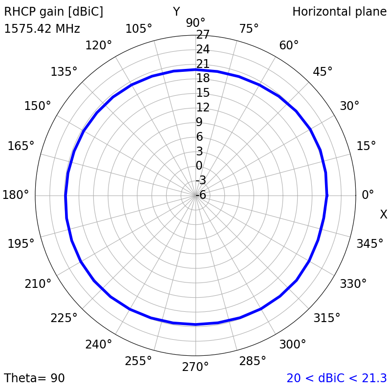
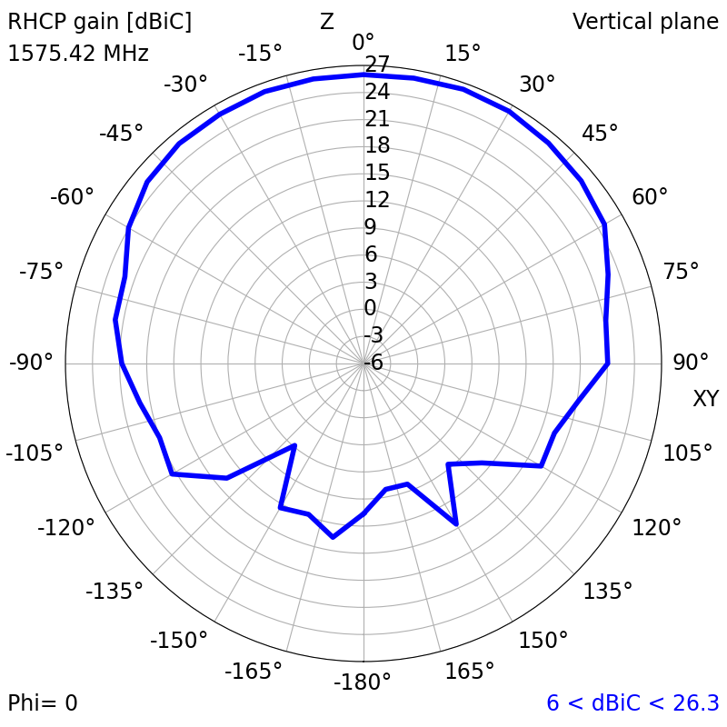
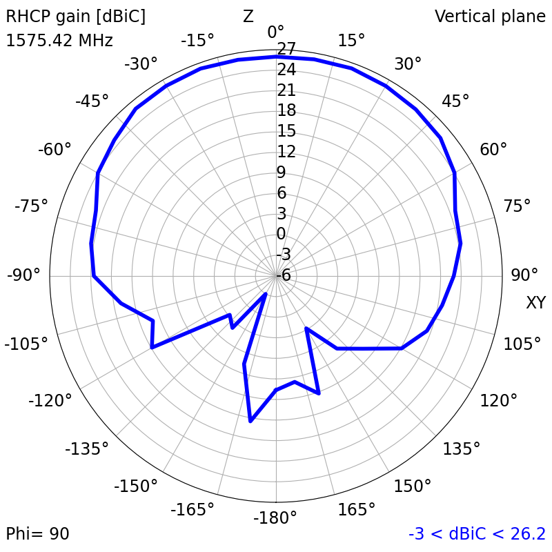
| 1575.42 MHz (L1) | ||
| XY | XZ | YZ |
|
|
|
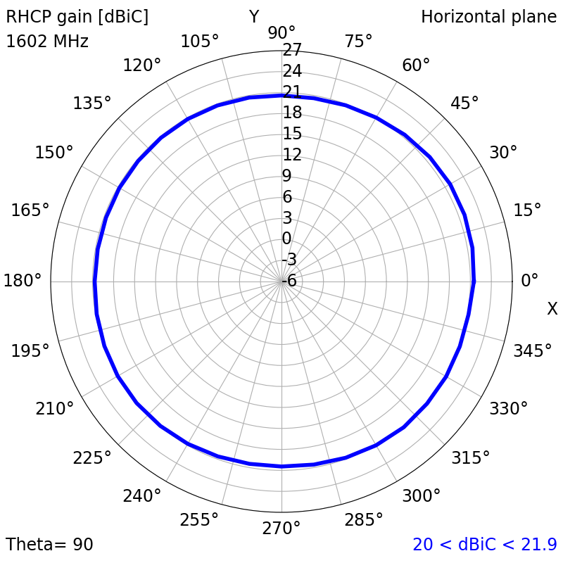
| 1602 MHz (L10F/C) | ||
| XY | XZ | YZ |
|
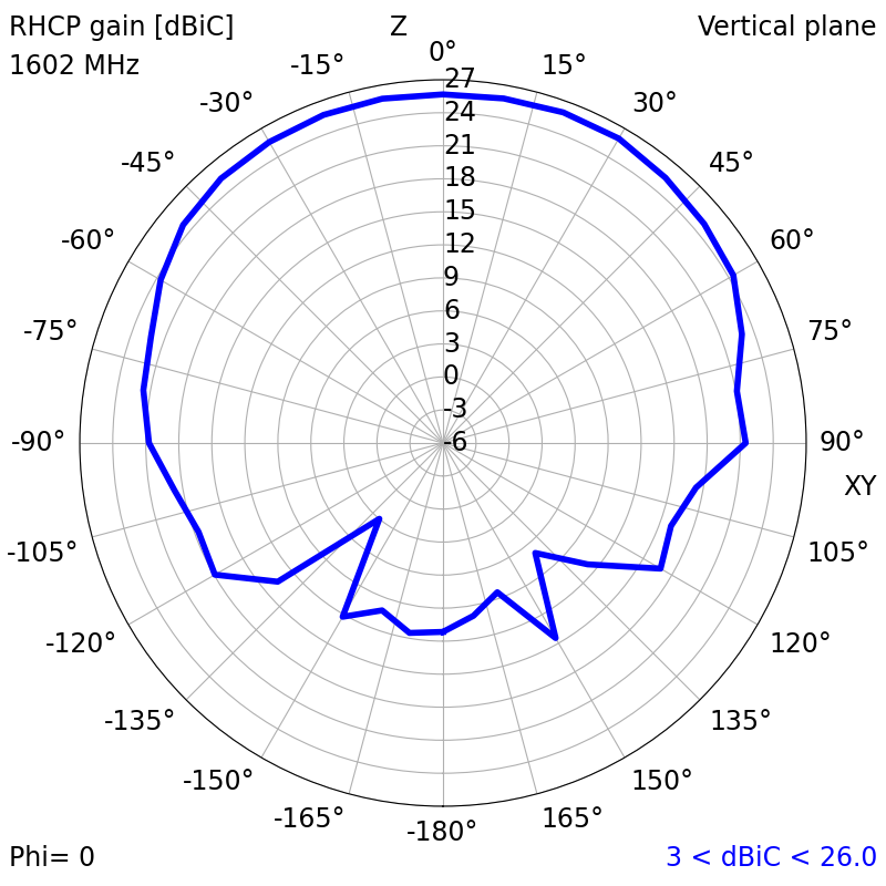
|
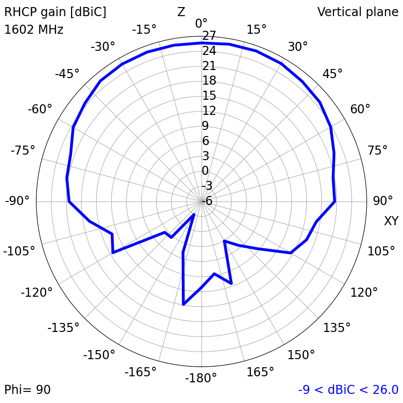
|
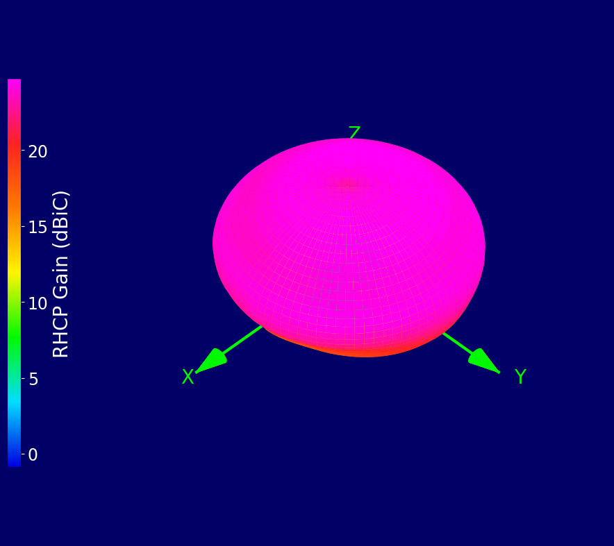
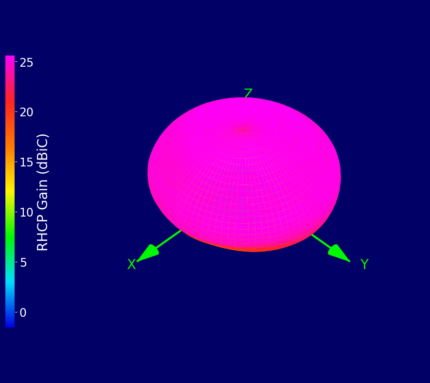
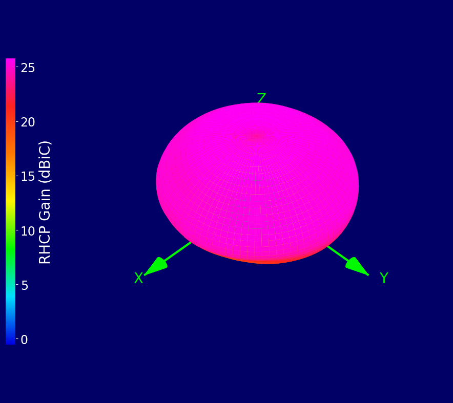
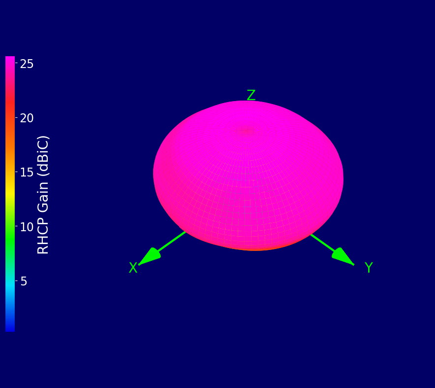
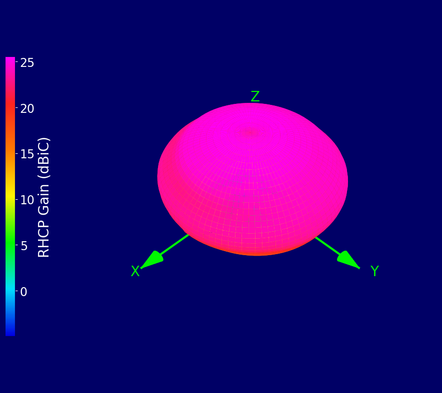
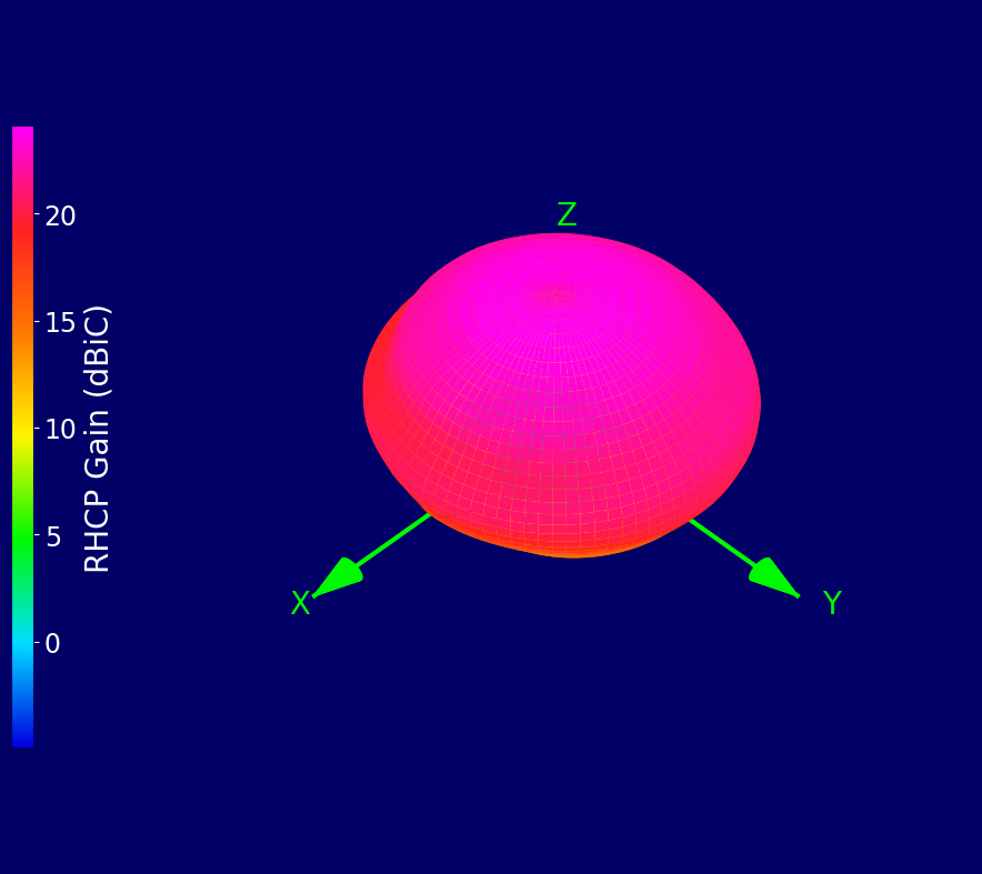
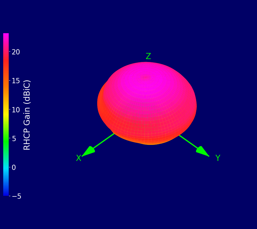
¶ 3D Radiation Plots
| 1176.45 MHz (L5) | 1202.025 MHz (L30C) | 1207.14 MHz (E5B) |
 |
 |
 |
| 1227.60 MHz (L2) | 1246 MHz (L20F/C) | 1268.52 MHz (B3I) |
 |
 |
 |
| 1278.750 MHz (E6-I/Q) | 1561.098 MHz (B1I) | 1575.420 MHz (L1) |
 |
 |
 |
| 1602 MHz (L10F/C) | ||
 |
¶ Ordering Details
| Part Number | Description |
|---|---|
| ECHO50/0.1M/SMAM/S/S/17 |
Active High Accuracy Ceramic Patch Multi-Band L1, L2, L5 & L6 Antenna 0.1 m Cable SMA Male Connector |
| ECHO50/0.1M/I-PEX/MHF1/S/17 |
Active High Accuracy Ceramic Patch Multi-Band L1, L2, L5 & L6 Antenna 0.1 m Cable I-PEX MHF1 Connector |
| ECHO50/0.1M/I-PEX/MHF4/S/17 |
Active High Accuracy Ceramic Patch Multi-Band L1, L2, L5 & L6 Antenna 0.1 m Cable I-PEX MHF4 Connector |