|
|
¶ General Description
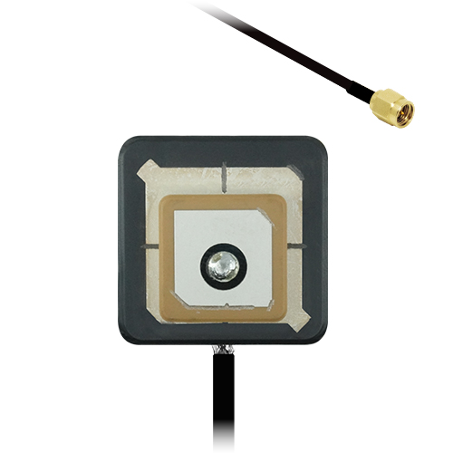
The Echo 52 is an embedded multi-band GNSS antenna that delivers high accuracy positioning across the L1 (1575 MHz), L2 (1227 MHz) and L5 (1176 MHz) bands. It supports all major constellations including GPS, Galileo, BeiDou, QZSS and NavIC, enabling broad global compatibility for navigation, location and timing applications.
Its stacked ceramic patch structure and two-stage LNA provide strong RHCP gain with excellent axial purity, yielding robust performance even in low-signal or multipath environments. The antenna’s directional pattern ensures maximum efficiency in the upper hemisphere, making it ideal for embedded GNSS modules and compact systems requiring precision tracking or RTK capability.
Available with MHF1/UMCC/U.FL or SMA connectors and 1.13 mm miniature coax cable as standard. Alternative lengths and connector types can be specified for high-volume orders.
¶ Key Features
- GNSS L1, L2, L5 & L6 coverage (1176–1602 MHz)
- Integrated 2-stage Low Noise Amplifier for strong signal reception and low noise figure (≤ 1.3 dB)
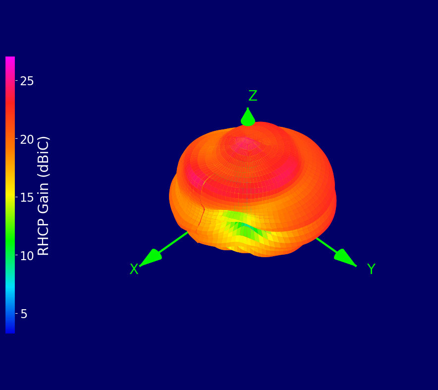
- Top-hemisphere RHCP gain up to 30 dBiC
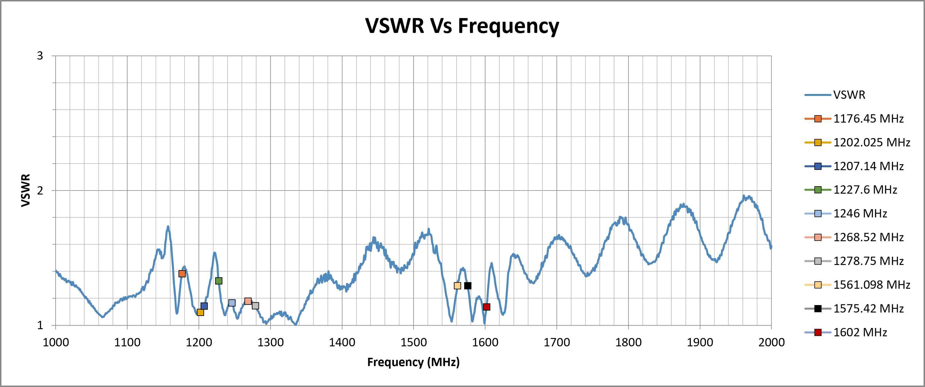
- Wideband GNSS coverage from 1176–1602 MHz with VSWR ≤ 1.4
- Compact 25 × 25 × 12.5 mm embedded ceramic design
¶ Typical Applications
- High-precision GNSS receivers and RTK modules
- UAV and drone navigation systems
- Automotive and smart transport applications
- Asset and fleet tracking devices
- Timing and synchronisation equipment
|
Multi-Band GNSS
1176–1602 MHz
|
Active Antenna
Integrated LNA
|
RHCP Gain
Up to 30 dBiC
|
Embedded
Installation
|
UAV Optimised
Ideal for Aerial Platforms
|
¶ Electrical Specifications
| Impedance: | 50 Ohm |
| Polarisation: | RHCP |
| Frequency Range: | 1176.45 – 1602 MHz |
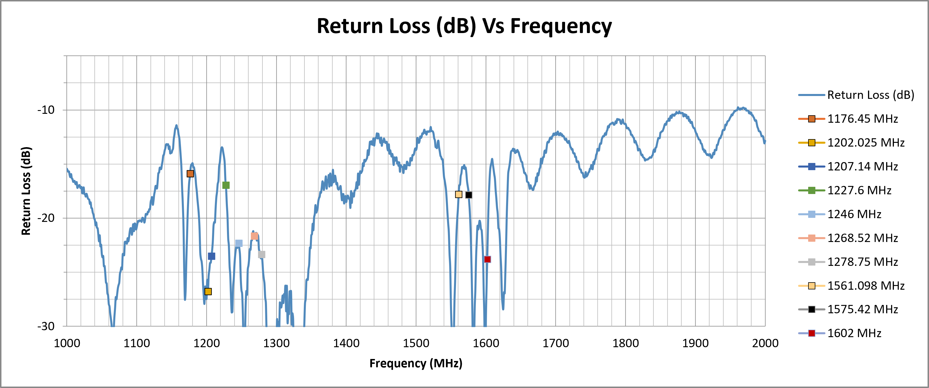
| Return Loss: | ≤ -15.89 dB |
| VSWR: | ≤ 1.4 |
| Required Ground Plane: | Free space |
| Peak RHCP Gain (Top Hemisphere): |
29.52 dBiC |
| Noise Figure: | ≤ 1.3 dB |
| Supply Voltage: | 2.7 – 3.3 V DC (typ. 3.0 V) |
| Current Consumption: | 10 ± 2 mA @ 3.0 V (≤ 15 mA @ 3.3 V) |
¶ Environmental Specifications
| Operating Temperature Range: | -40 °C to +85 °C |
| Storage Temperature Range: | -40 °C to +85 °C |
| ESD Protection: | 2 kV HBM |
| Ingress Protection: | None |
¶ Mechanical Specifications
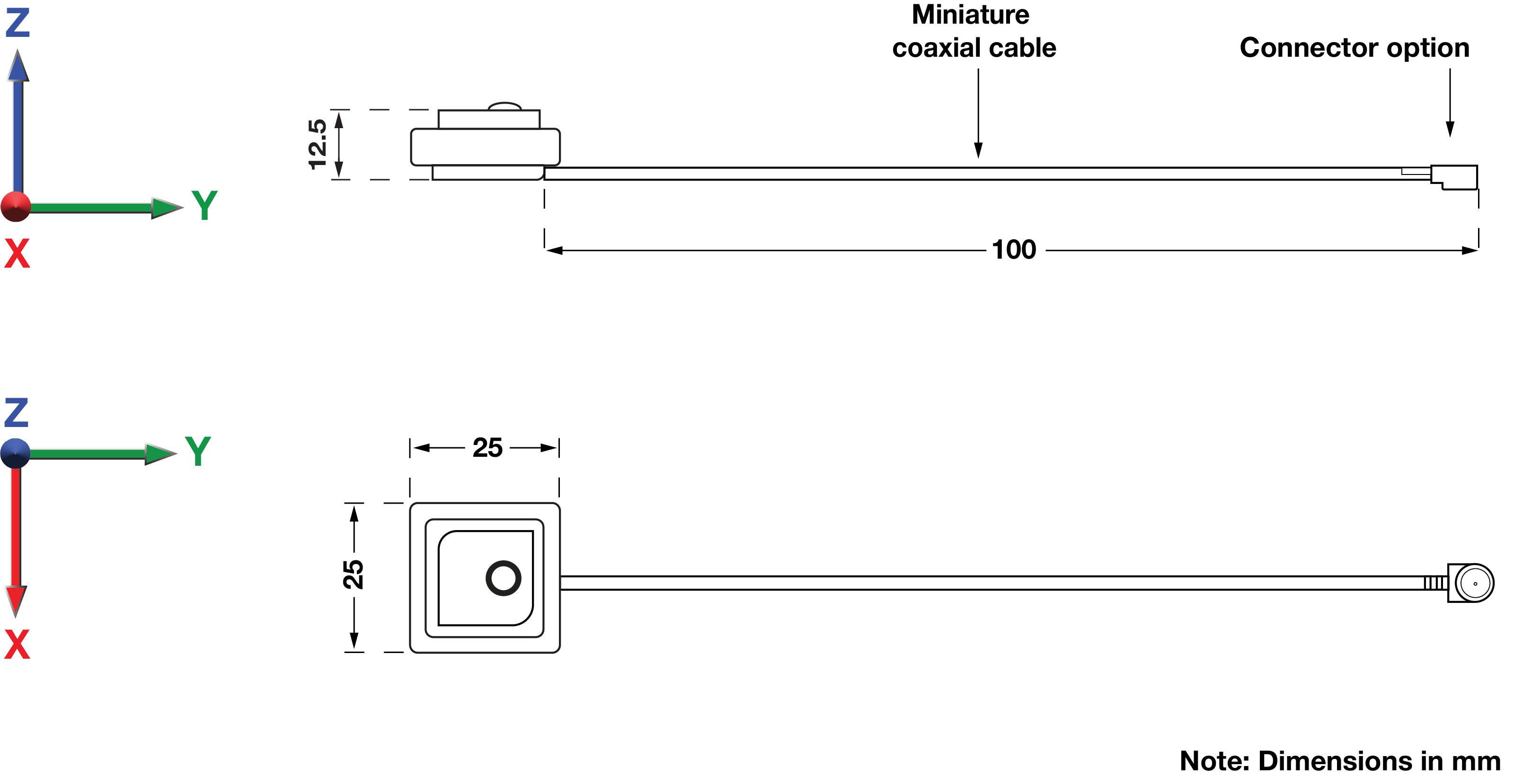
| Dimensions: | 25 × 25 × 12.5 mm |
| Weight: | 18.5 g |
| Connector: | MHF1 / UMCC / U.FL / SMA Male |
| Cable: | 1.13 mm mini coax |
| Mounting Method: | Embedded – adhesive or mechanical fixing (adhesive not supplied) |
| Material: | Stacked Ceramic Patch (Upper Yellow / Lower Black) |
¶ Spectrum Coverage*
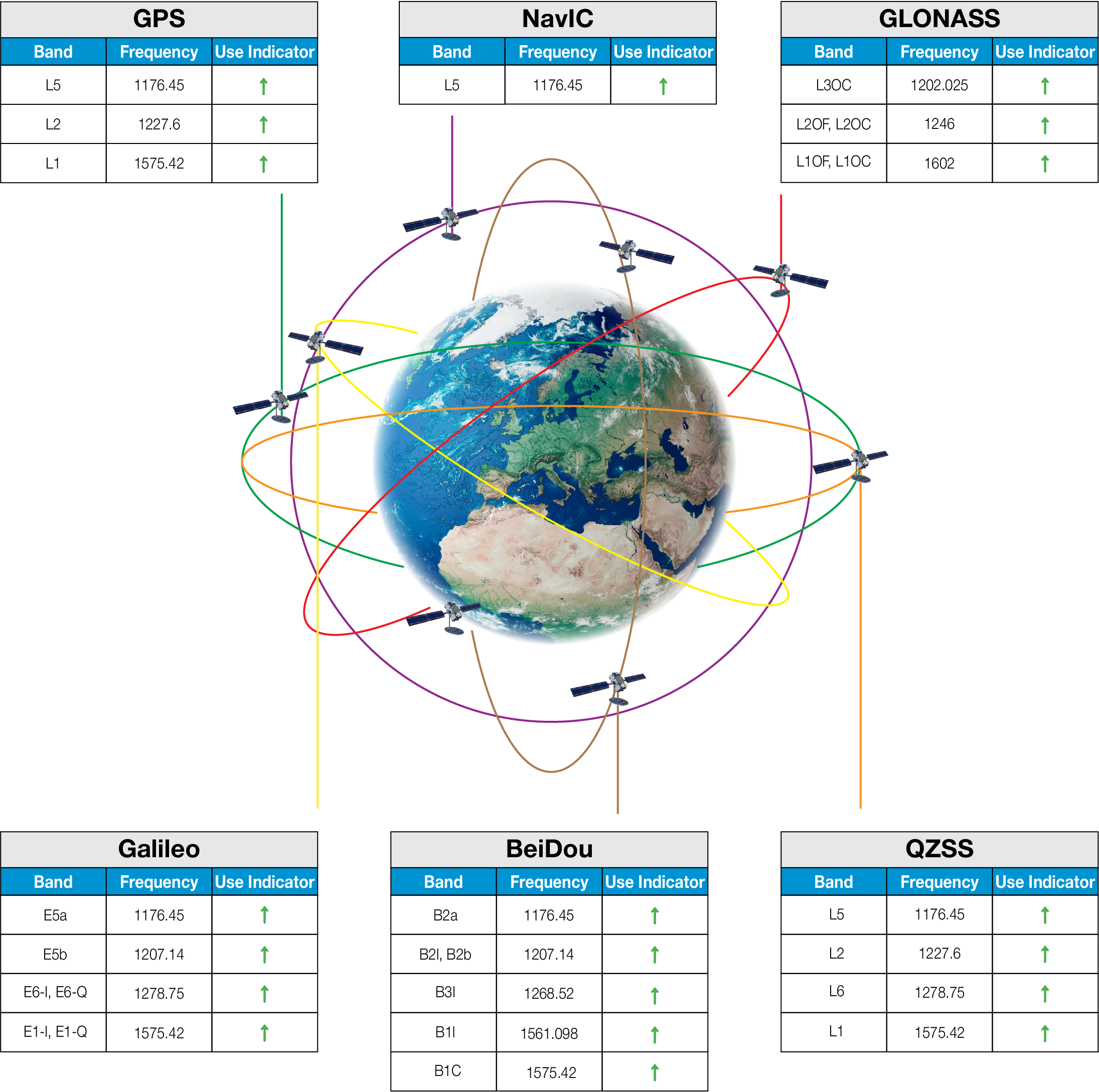
| ↑ Suitable band | □ Adequate band in good signal conditions | ↓ Likely to be unsuitable |
¶ GNSS Standards Band Support
| Electrical Interface | Spherical RF Measurements | |||||
|---|---|---|---|---|---|---|
| Centre Frequency (MHz) | VSWR | Return Loss (dB) | Average RHCP Gain (dBiC) | Peak RHCP Gain (dBiC) | Median Axial Ratio (dB) | Minimum Axial Ratio (dB) |
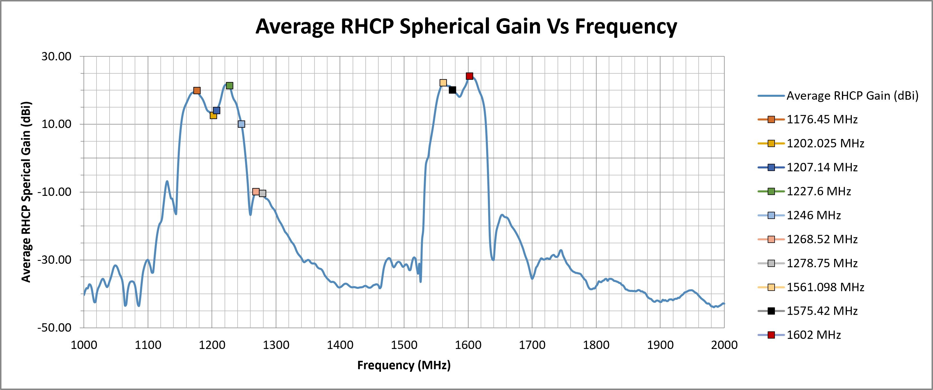
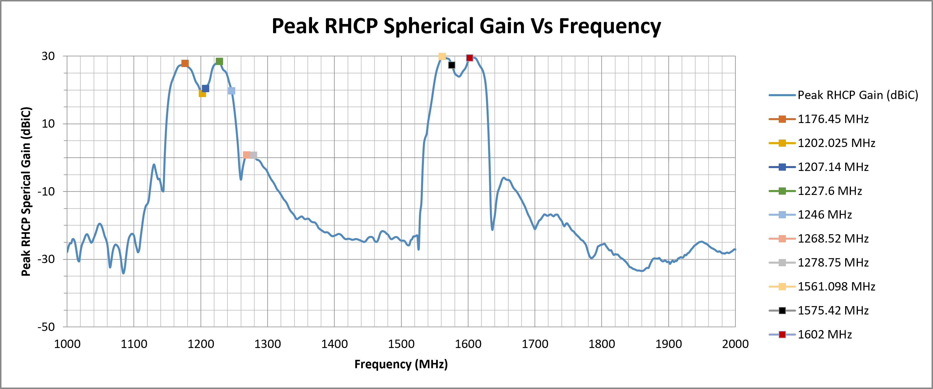
| 1176.45 | 1.3830 | -15.8899 | 19.97 | 27.94 | 18.77 | 1.32 |
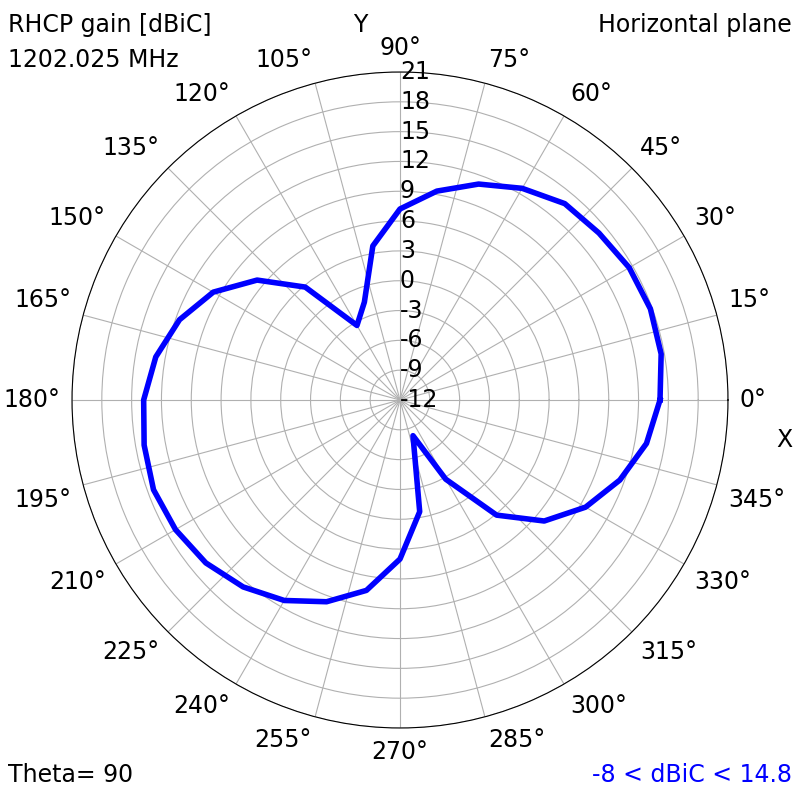
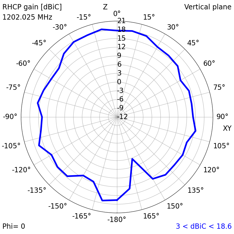
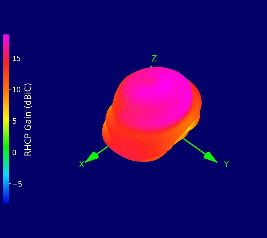
| 1202.025 | 1.0960 | -26.7892 | 12.65 | 19.04 | 21.34 | 1.03 |
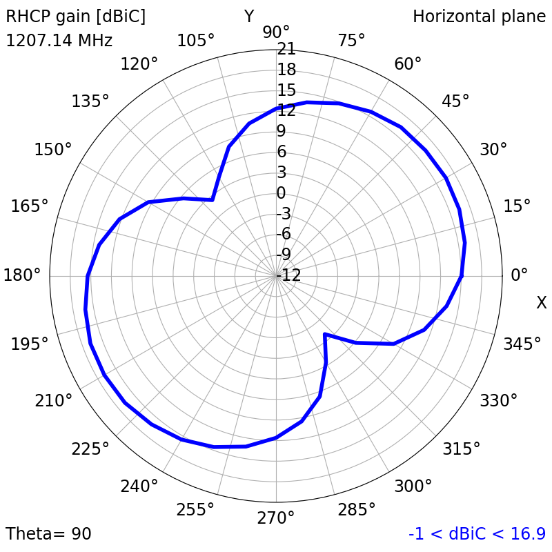
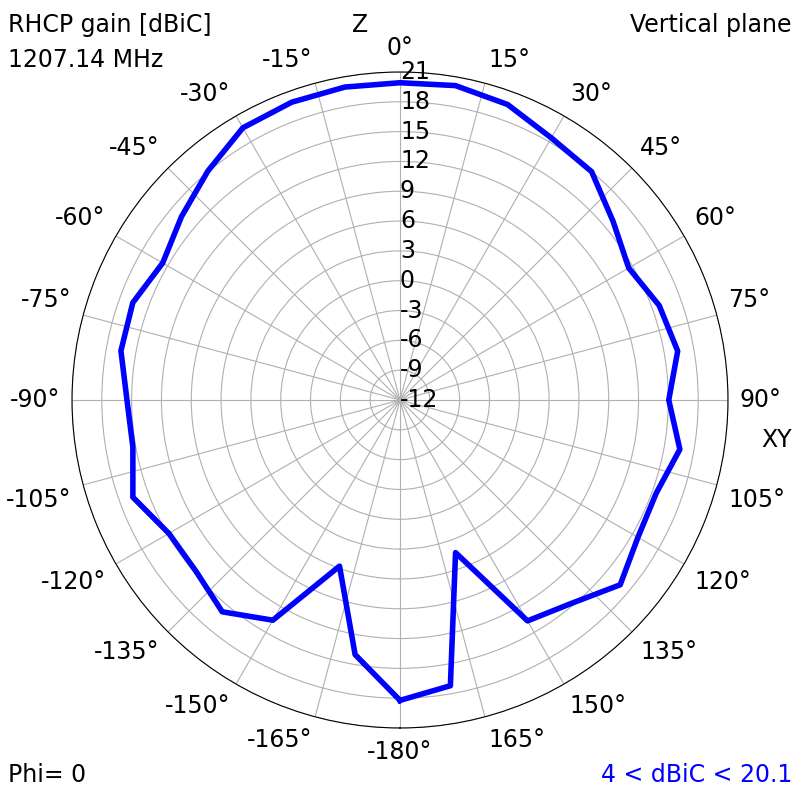
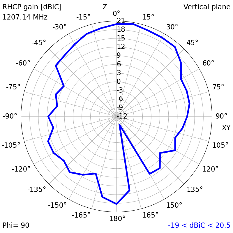
| 1207.14 | 1.1433 | -23.5012 | 14.05 | 20.49 | 20.00 | 0.68 |
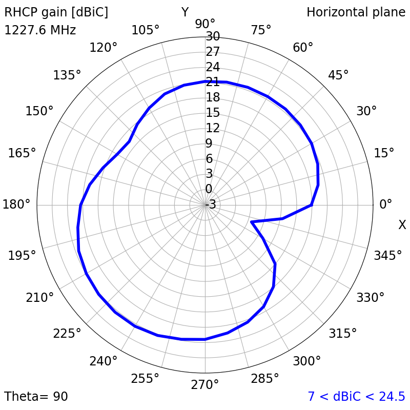
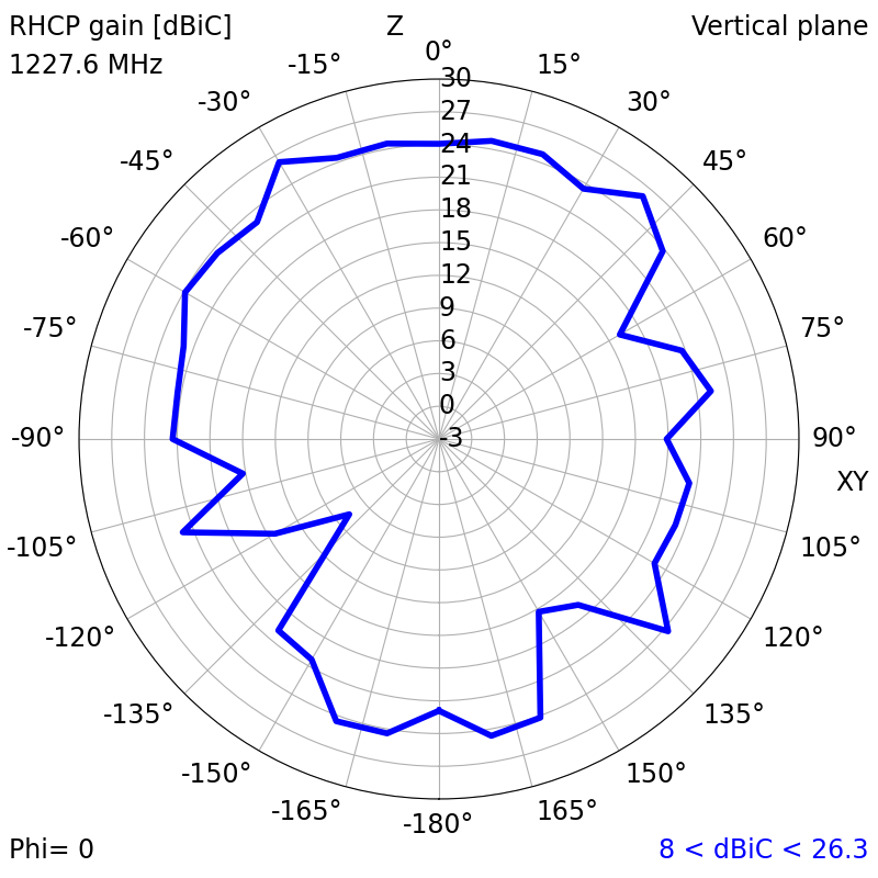
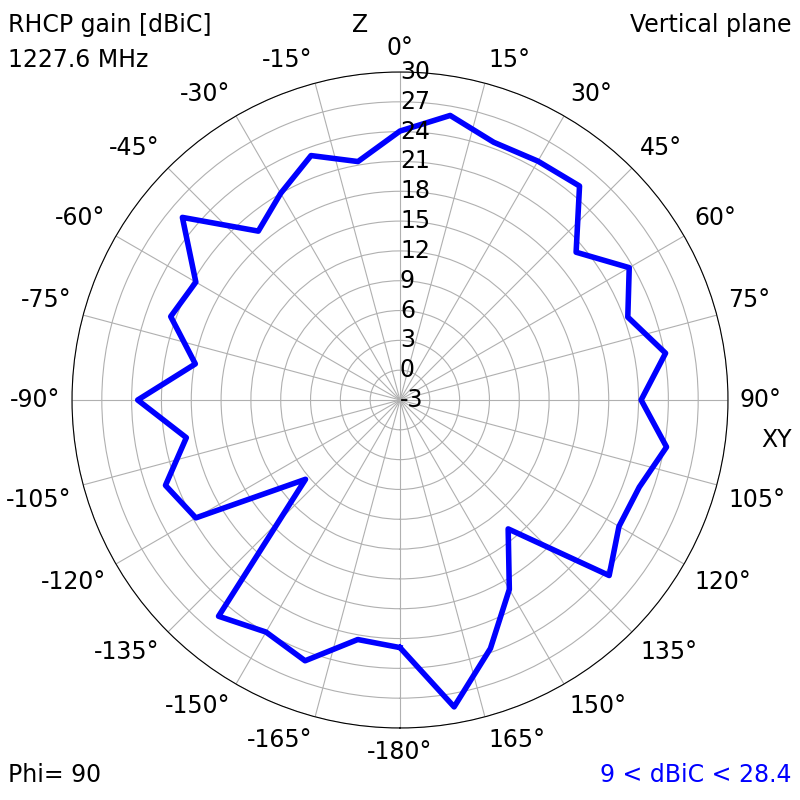
| 1227.6 | 1.3315 | -16.9542 | 21.40 | 28.53 | 15.82 | 1.20 |
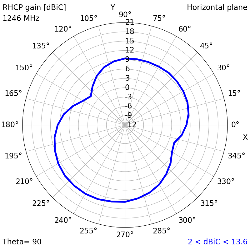
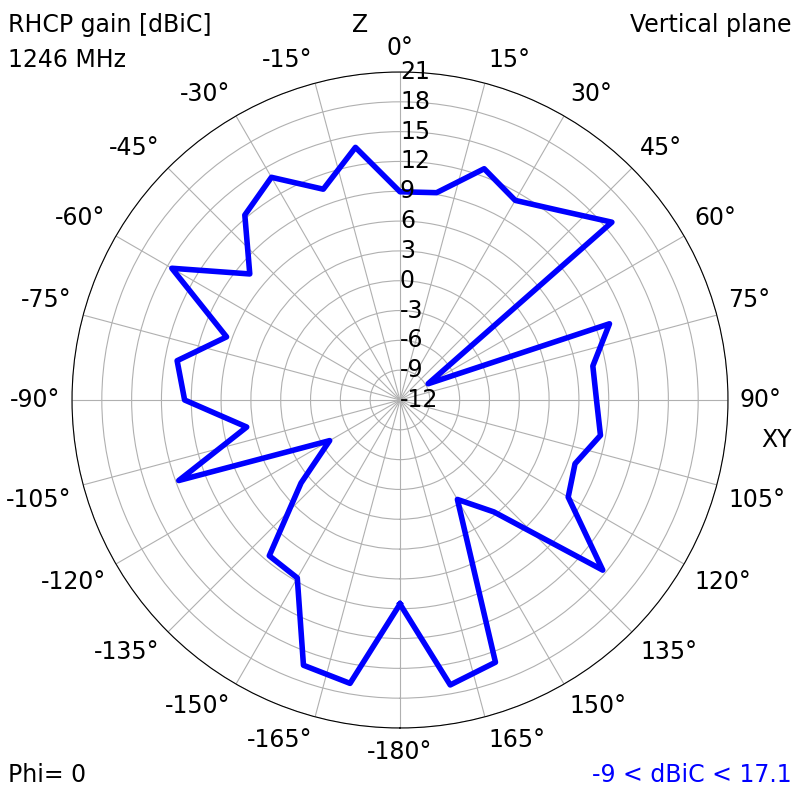
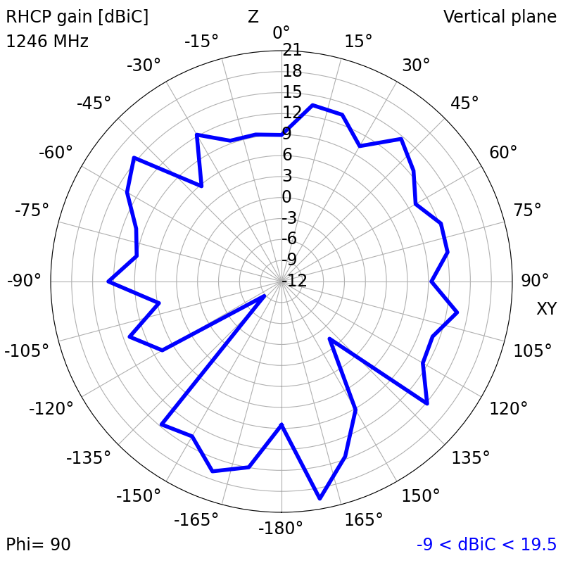
| 1246 | 1.1661 | -22.3046 | 10.10 | 19.76 | 15.42 | 0.32 |
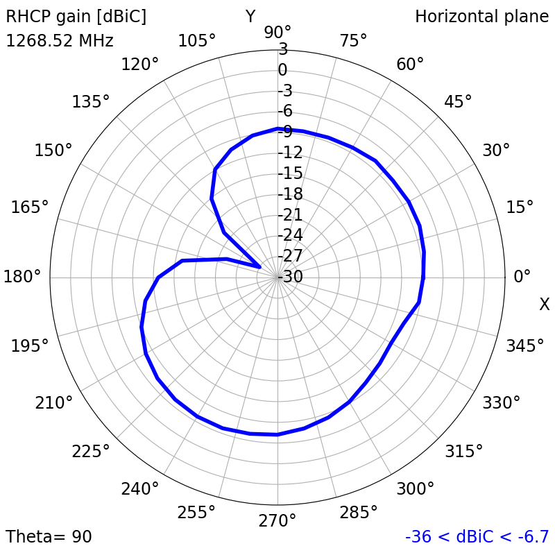
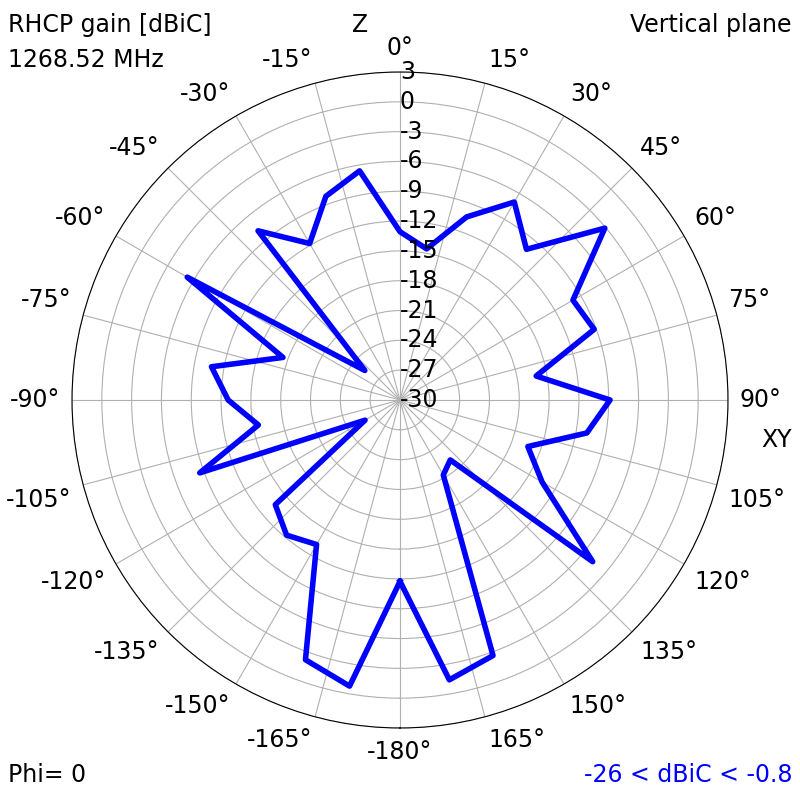
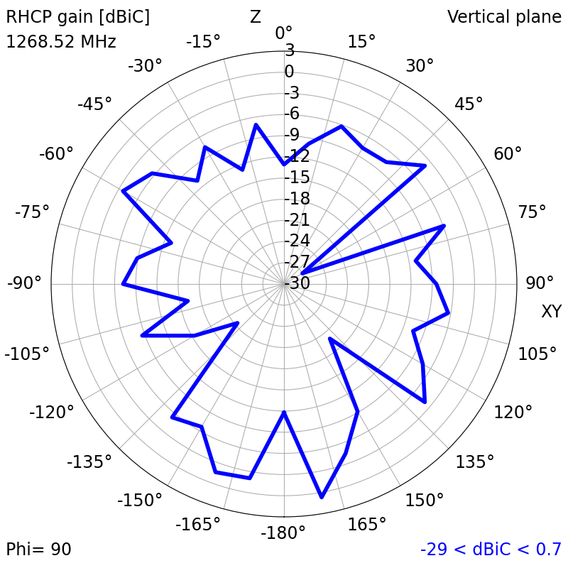
| 1268.52 | 1.1803 | -21.6524 | -9.88 | 0.87 | 14.13 | 0.77 |
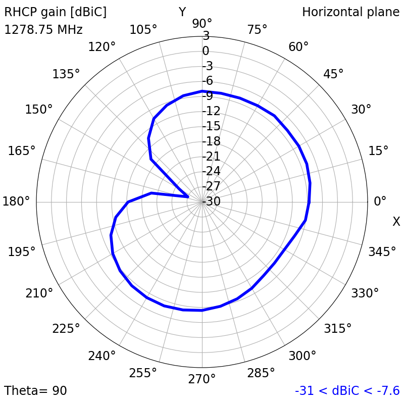
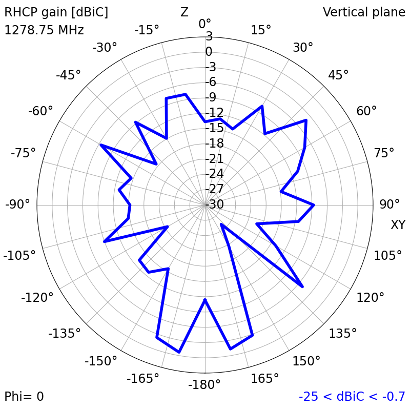
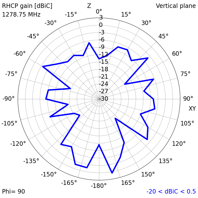
| 1278.75 | 1.1462 | -23.3394 | -10.31 | 0.76 | 12.56 | 1.39 |
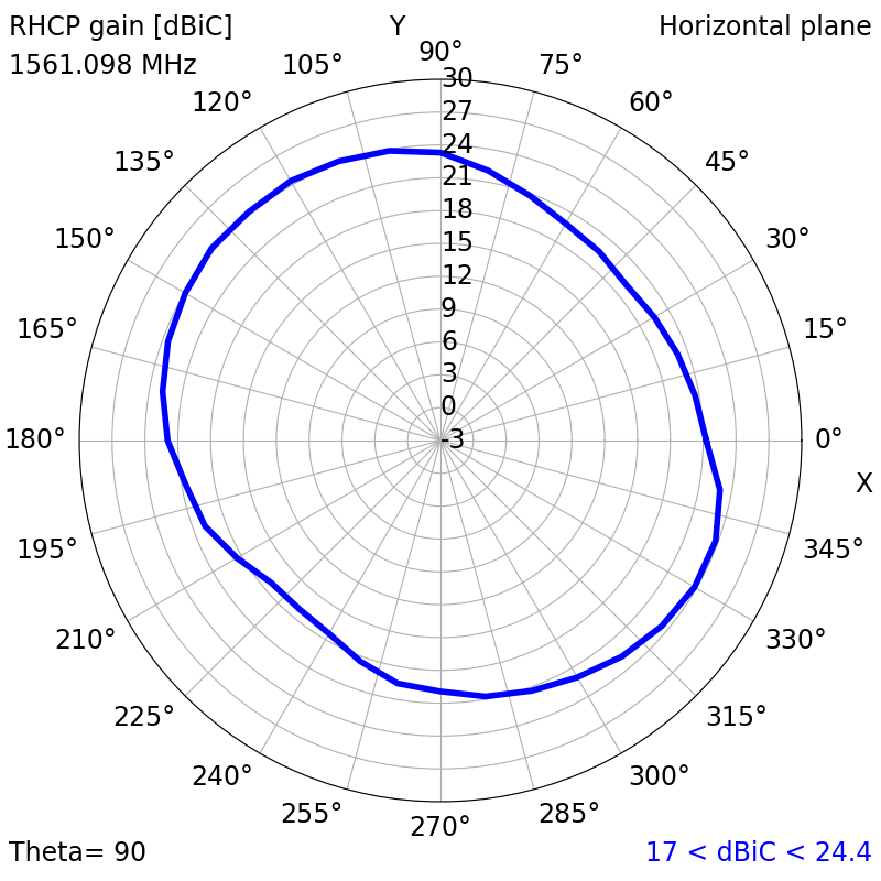
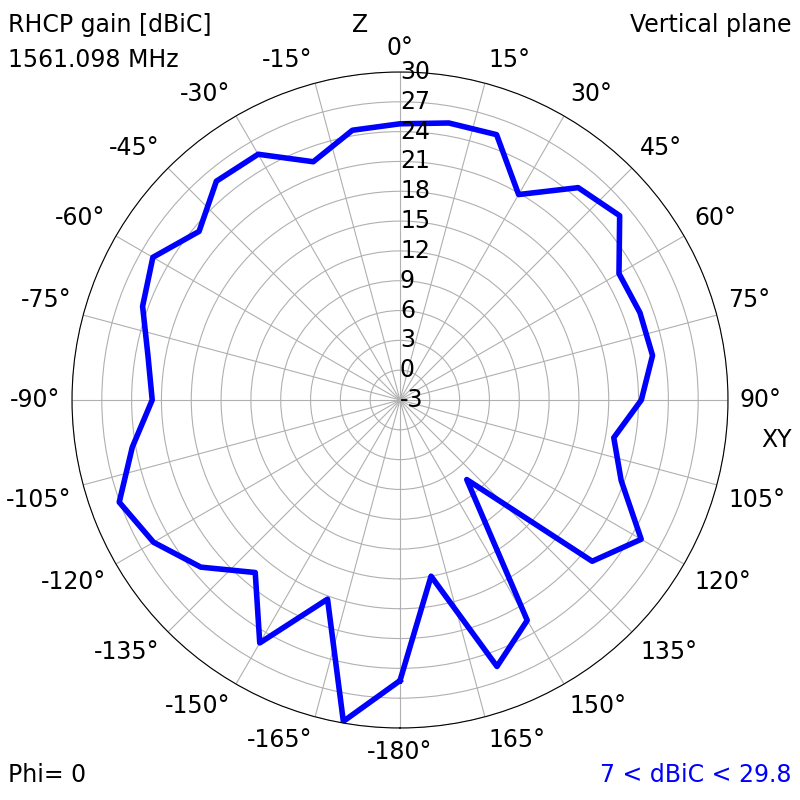
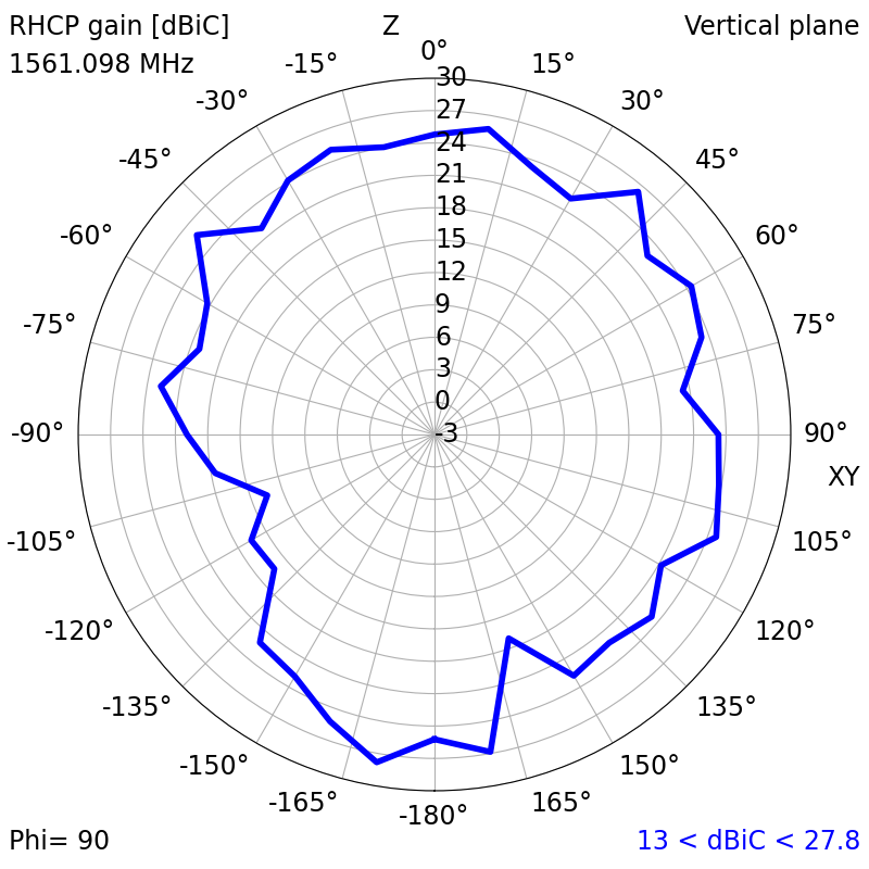
| 1561.098 | 1.2957 | -17.8084 | 22.23 | 29.92 | 17.26 | 0.43 |
| 1575.42 | 1.2942 | -17.8560 | 20.10 | 27.36 | 19.11 | 0.18 |
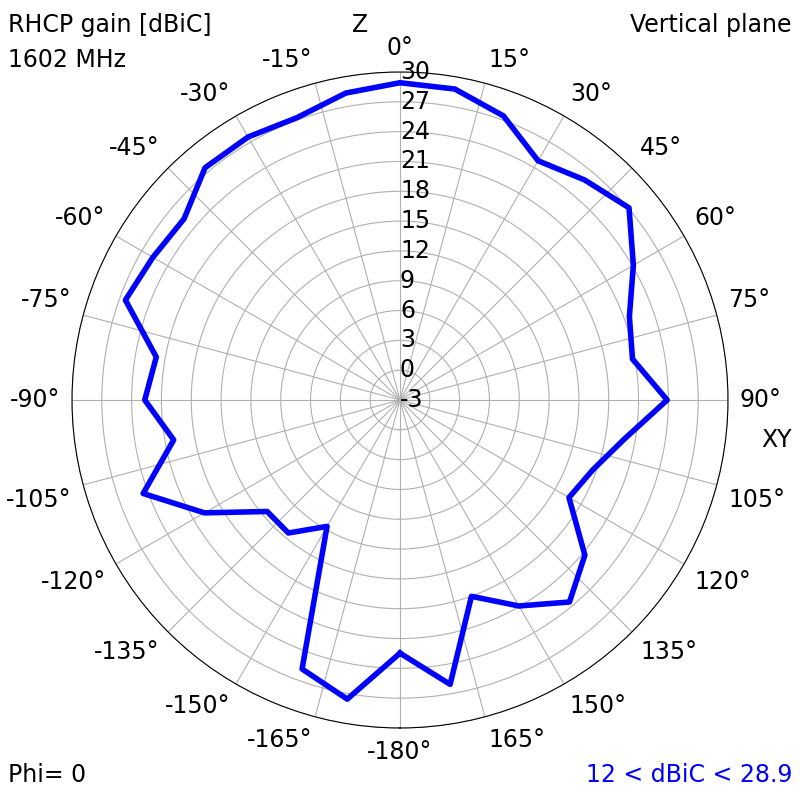
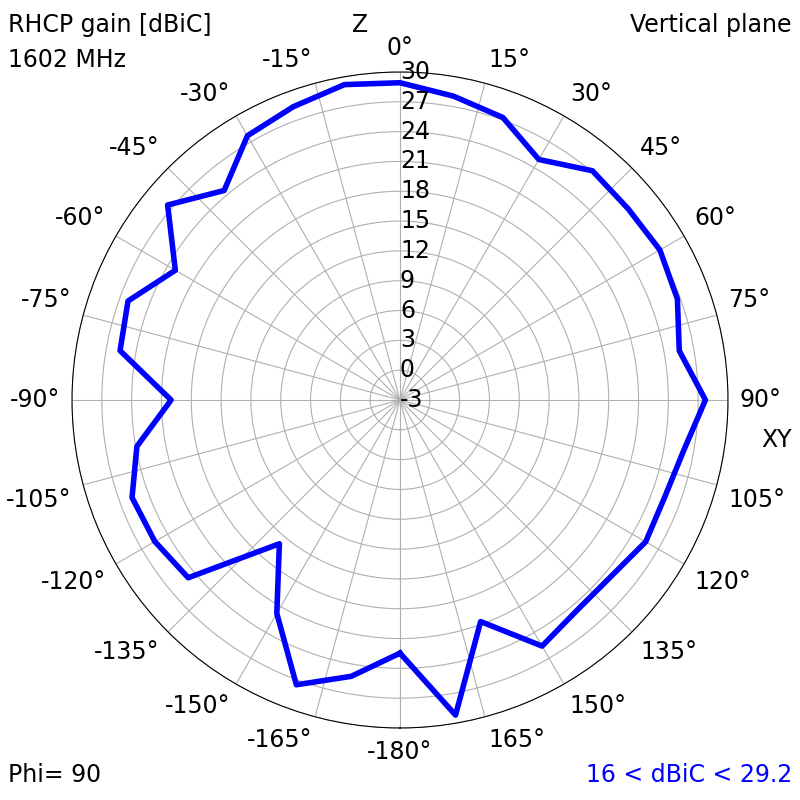
| 1602 | 1.1381 | -23.7943 | 24.23 | 29.52 | 13.04 | 0.73 |
| Top Hemisphere RF Measurements | Zenith RF Measurements | |||||
|---|---|---|---|---|---|---|
| Centre Frequency (MHz) | Average RHCP Gain (dBiC) | Peak RHCP Gain (dBiC) | Median Axial Ratio (dB) | Minimum Axial Ratio (dB) | RHCP Gain at Zenith (dBiC) | Axial Ratio at Zenith (dB) |
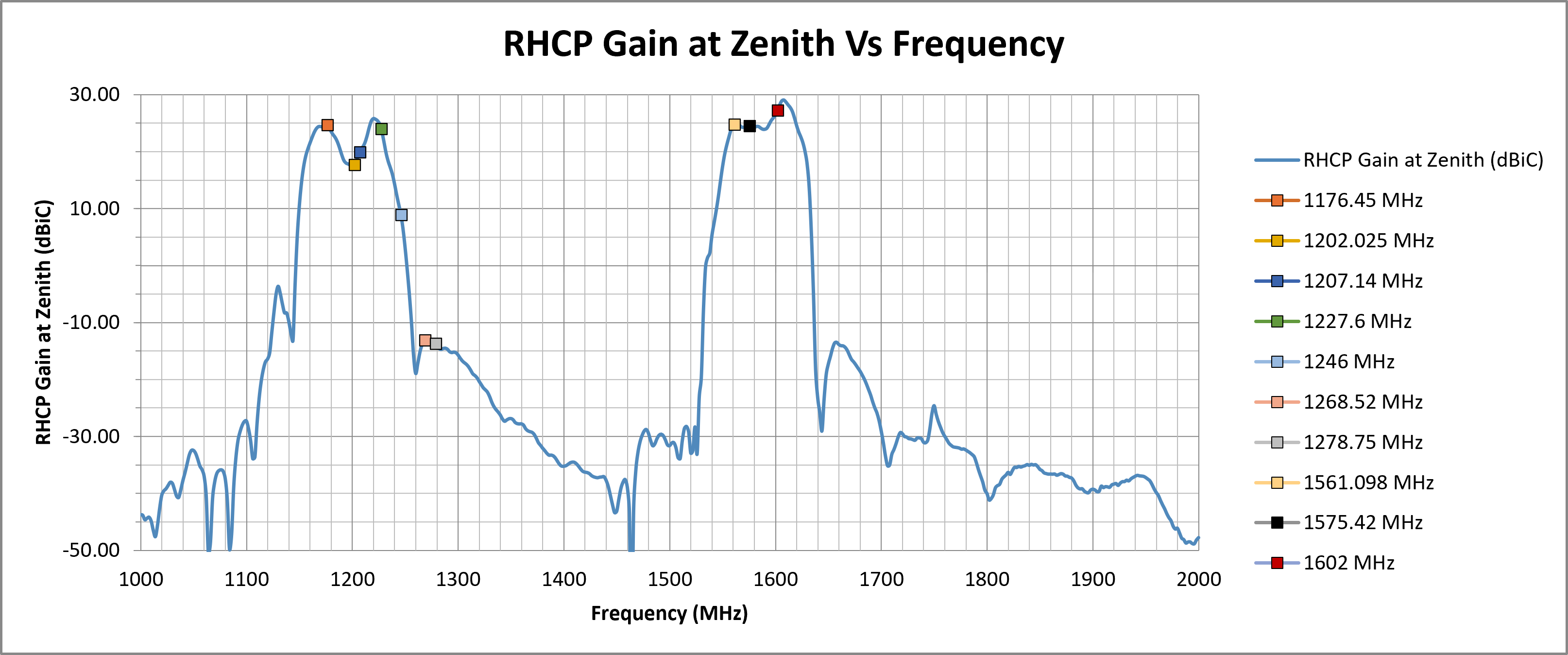
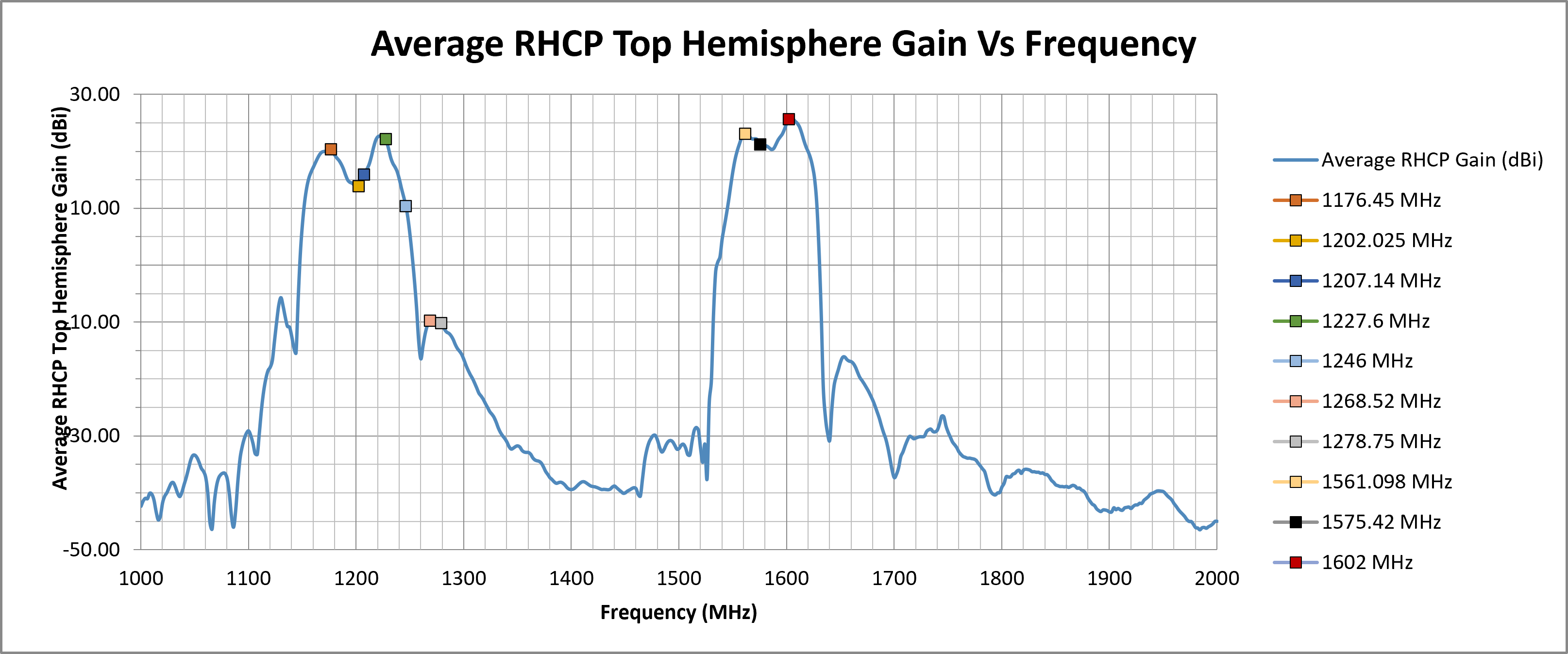
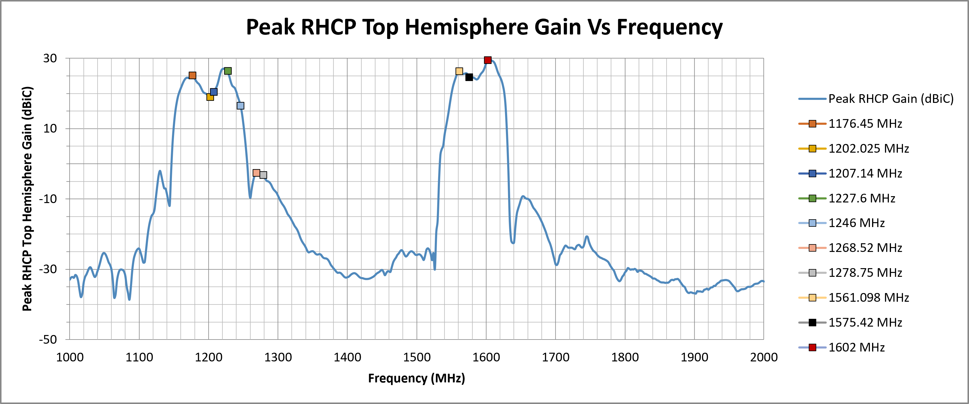
| 1176.45 | 20.42 | 25.15 | 20.93 | 1.90 | 24.70 | 42.13 |
| 1202.025 | 13.88 | 19.04 | 23.83 | 1.03 | 17.72 | 33.98 |
| 1207.14 | 15.95 | 20.49 | 20.88 | 1.55 | 19.92 | 18.34 |
| 1227.6 | 22.15 | 26.43 | 16.51 | 1.20 | 24.06 | 14.77 |
| 1246 | 10.45 | 16.56 | 18.03 | 0.32 | 8.95 | 9.50 |
| 1268.52 | -9.71 | -2.57 | 15.59 | 1.08 | -13.07 | 18.87 |
| 1278.75 | -10.17 | -3.18 | 14.90 | 1.75 | -13.66 | 21.01 |
| 1561.098 | 23.16 | 26.36 | 19.68 | 1.87 | 24.79 | 17.98 |
| 1575.42 | 21.23 | 24.65 | 22.99 | 4.68 | 24.56 | 36.34 |
| 1602 | 25.73 | 29.52 | 12.62 | 3.05 | 27.23 | 10.46 |
¶ RF Matching Performance
This section illustrates the antenna's impedance matching characteristics across the operating frequency range using VSWR and Return Loss measurements.
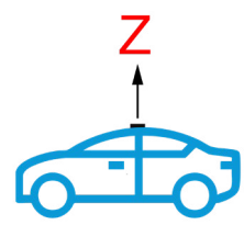
¶ RF Zenith
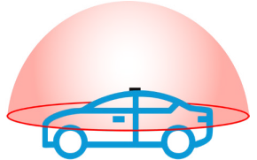
¶ RF Top Hemisphere
¶ RF Spherical
The following graphs display the Average and Peak RHCP Gain across the entire spherical coverage of the antenna. These metrics provide a comprehensive view of the antenna’s ability to receive signals from satellites at all elevations and directions.
Consistently high gain across the sphere ensures strong and stable GNSS reception in a variety of operating conditions.

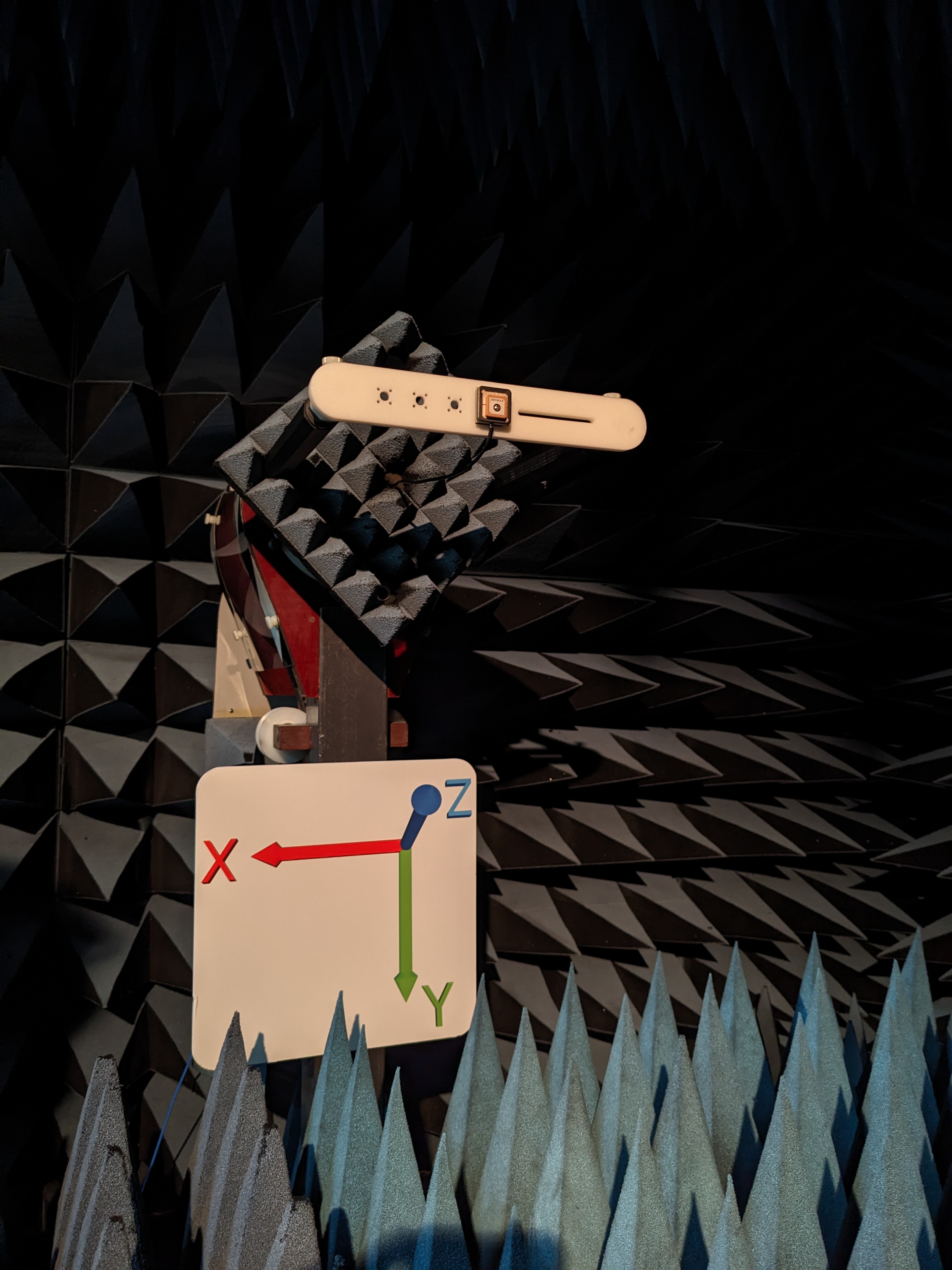
¶ Test Setup (in Free Space)
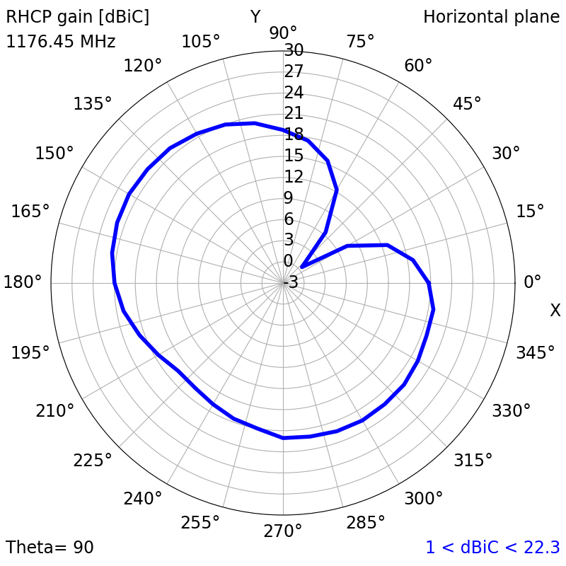
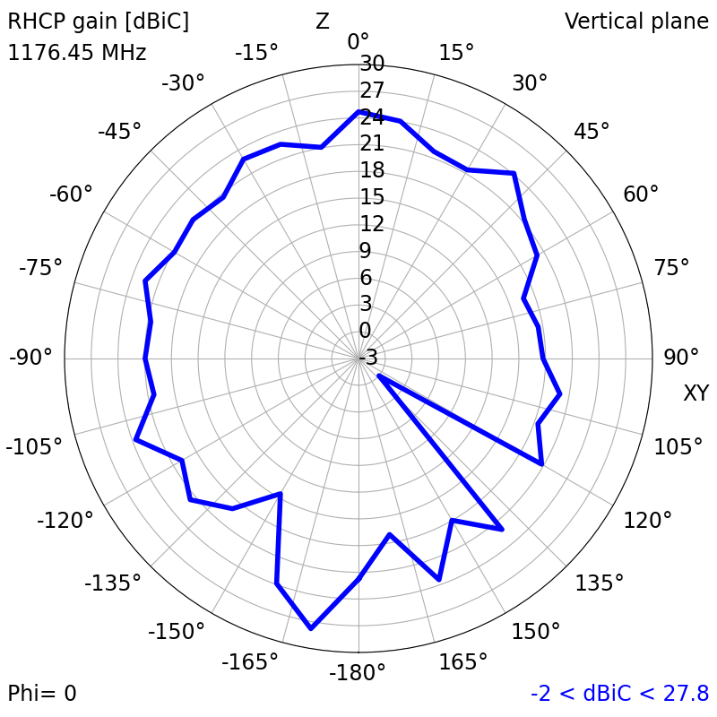
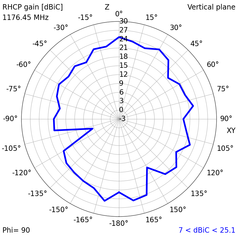
¶ 2D Radiation Plots
| 1176.45 MHz | ||
| XY | XZ | YZ |
|
|
|
| 1202.025 MHz | ||
| XY | XZ | YZ |
|
|
|
| 1207.14 MHz | ||
| XY | XZ | YZ |
|
|
|
| 1227.6 MHz | ||
| XY | XZ | YZ |
|
|
|
| 1246 MHz | ||
| XY | XZ | YZ |
|
|
|
| 1268.52 MHz | ||
| XY | XZ | YZ |
|
|
|
| 1278.75 MHz | ||
| XY | XZ | YZ |
|
|
|
| 1561.098 MHz | ||
| XY | XZ | YZ |
|
|
|
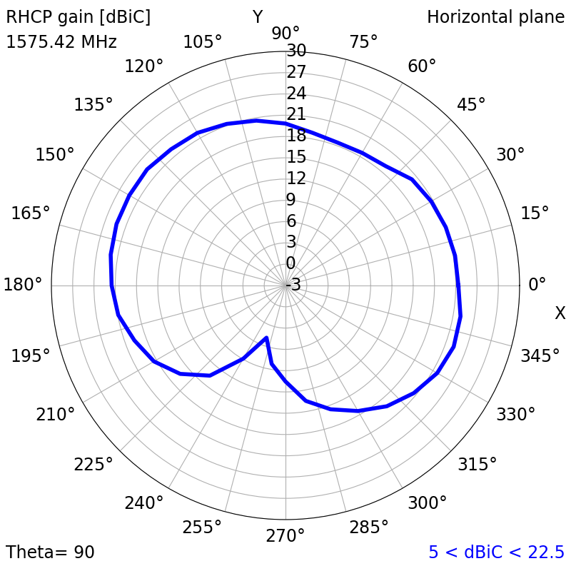
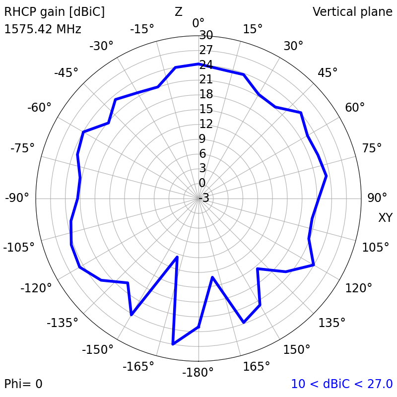
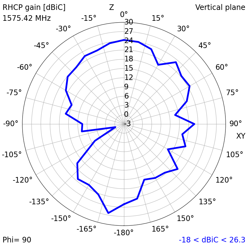
| 1575.42 MHz | ||
| XY | XZ | YZ |
|
|
|
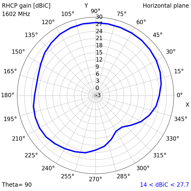
| 1602 MHz | ||
| XY | XZ | YZ |
|
|
|
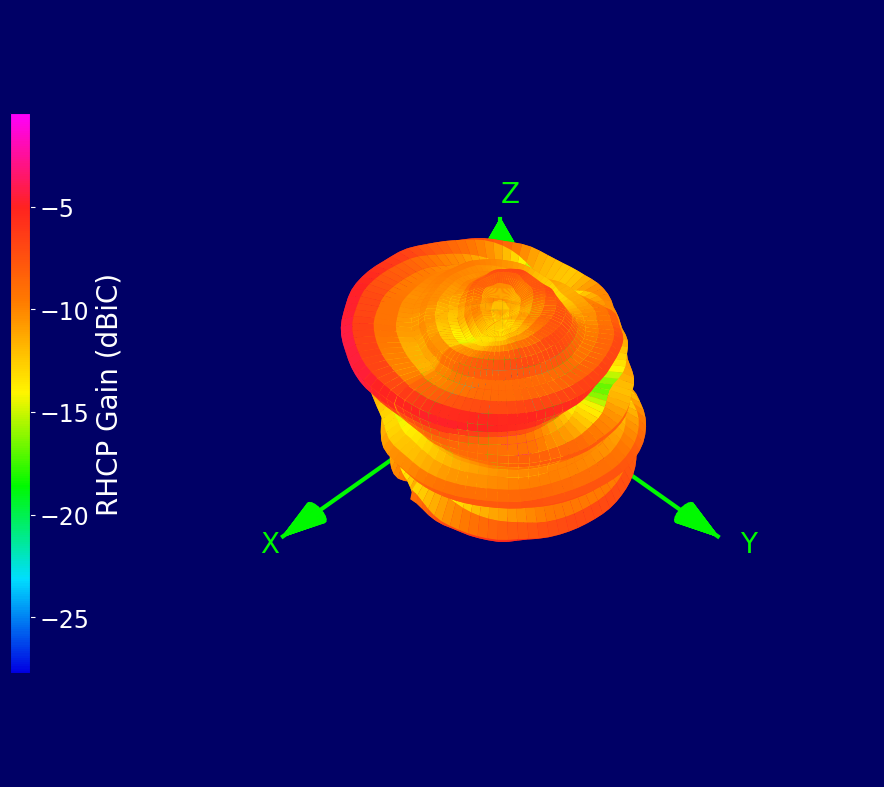
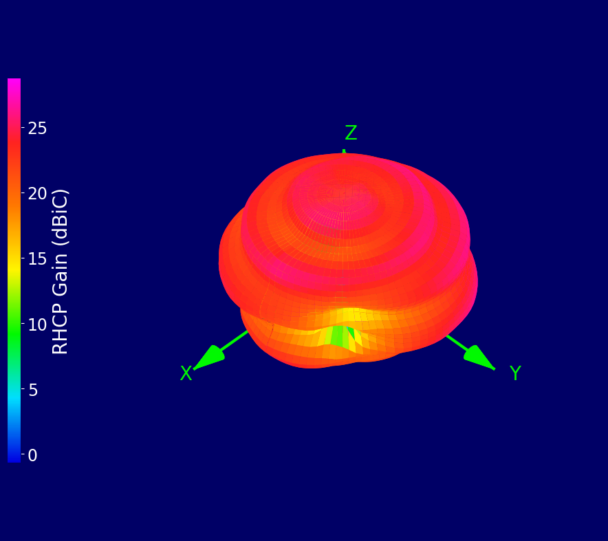
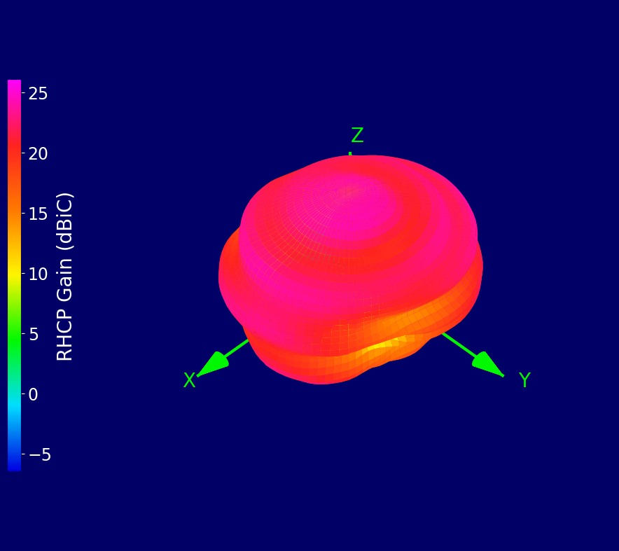
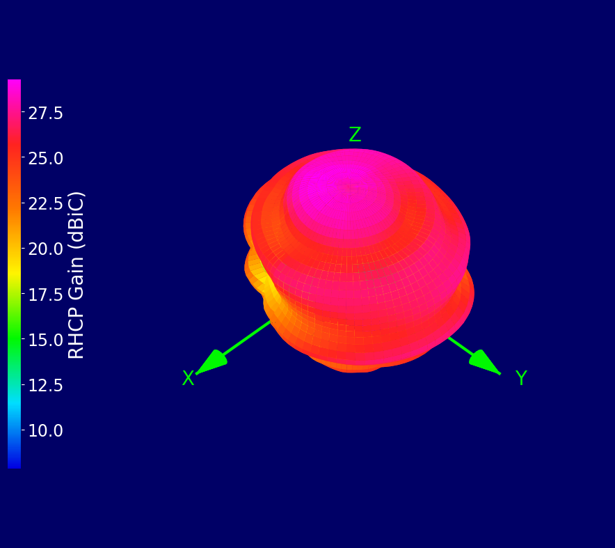
¶ 3D Radiation Plots
| 1176.45 MHz | 1202.025 MHz | 1207.14 MHz |
 |
 |
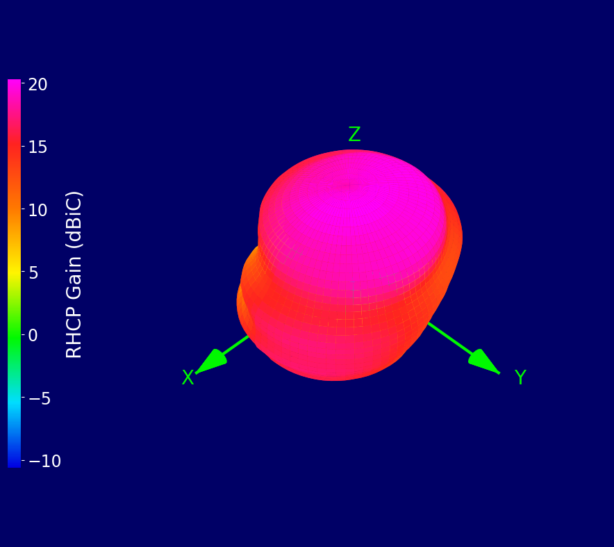 |
| 1227.60 MHz | 1246 MHz | 1268.52 MHz |
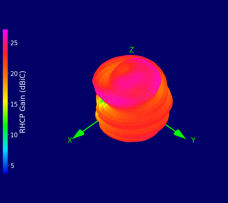 |
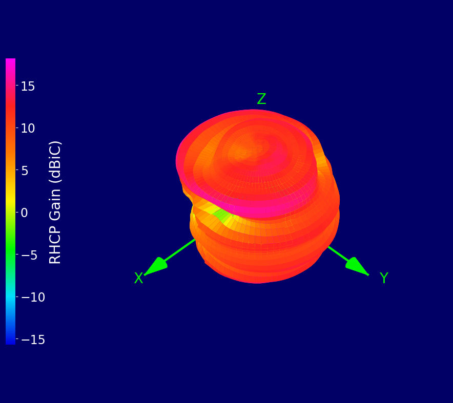 |
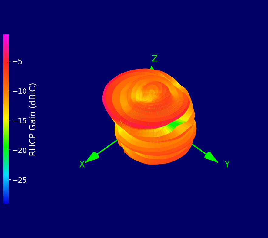 |
| 1278.750 MHz | 1561.098 MHz | 1575.420 MHz |
 |
 |
 |
| 1602 MHz | ||
 |
¶ Ordering Details
| Part Number | Description |
|---|---|
| ECHO52/0.1M/UFL/S/S/28 |
Compact Active High Accuracy Ceramic Patch Multi-Band L1, L2, L5 & L6 Antenna 0.1 m Cable and U.FL Connector |
| ECHO52/0.1M/MHF4/S/S/28 |
Compact Active High Accuracy Ceramic Patch Multi-Band L1, L2, L5 & L6 Antenna 0.1 m Cable and MHF4 Connector |
| ECHO52/1M/SMAM/S/S/32 |
Compact Active High Accuracy Ceramic Patch Multi-Band L1, L2, L5 & L6 Antenna 1 m Cable and SMA Male Connector |
| ECHO52/3M/SMAM/S/S/32 |
Compact Active High Accuracy Ceramic Patch Multi-Band L1, L2, L5 & L6 Antenna 3 m Cable and SMA Male Connector |