|
|
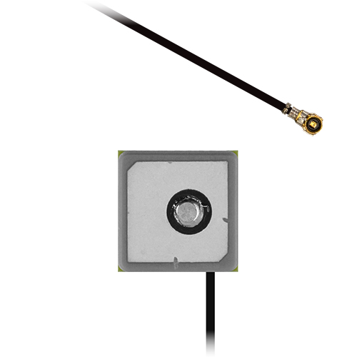
¶ General Description
The Echo 63 is a compact active GPS L1 antenna engineered for high-quality reception of satellite signals at 1575.42 MHz. Developed for positioning and navigation applications, it combines a small footprint with straightforward integration into embedded products.
Optimised for the primary GNSS L1 band, the Echo 63 incorporates an integrated low-noise amplifier (LNA) to amplify weak satellite signals at the antenna, helping preserve signal quality before transmission to the GNSS receiver. Delivering RHCP gain of 14 dBiC, together with good impedance matching, it supports stable satellite tracking and accurate position updates.
Weighing less than 4 grams, the Echo 63 is ideal for UAVs and portable equipment where minimising weight helps maximise flight time, payload capacity and overall efficiency. Its omnidirectional radiation pattern and lightweight form factor make it well suited to handheld surveying equipment, compact IoT sensors, drones and portable GPS terminals.
¶ Key Features
- Supports GPS L1, Galileo E1, BeiDou B1C, and QZSS L1
- Lightweight construction (under 4 g)
- 14 dBiC RHCP top hemisphere gain
- Omnidirectional radiation pattern for consistent sky coverage
- Compact design for easy integration
¶ Typical Applications
- Asset tracking and logistics
- Industrial IoT and remote monitoring
- UAV navigation and control
- Smart agriculture and precision farming
- Timing and synchronisation systems
|
GPS
L1 Antenna
|
UAV Optimised
Ideal for Aerial Platforms
|
Embedded
Installation
|
RHCP Gain
14 dBiC
|
Active
Integrated LNA
|
¶ Electrical Specifications
| Impedance: | 50 Ohm |
| Polarisation: | RHCP |
| Frequency Range: | 1575.42 MHz |
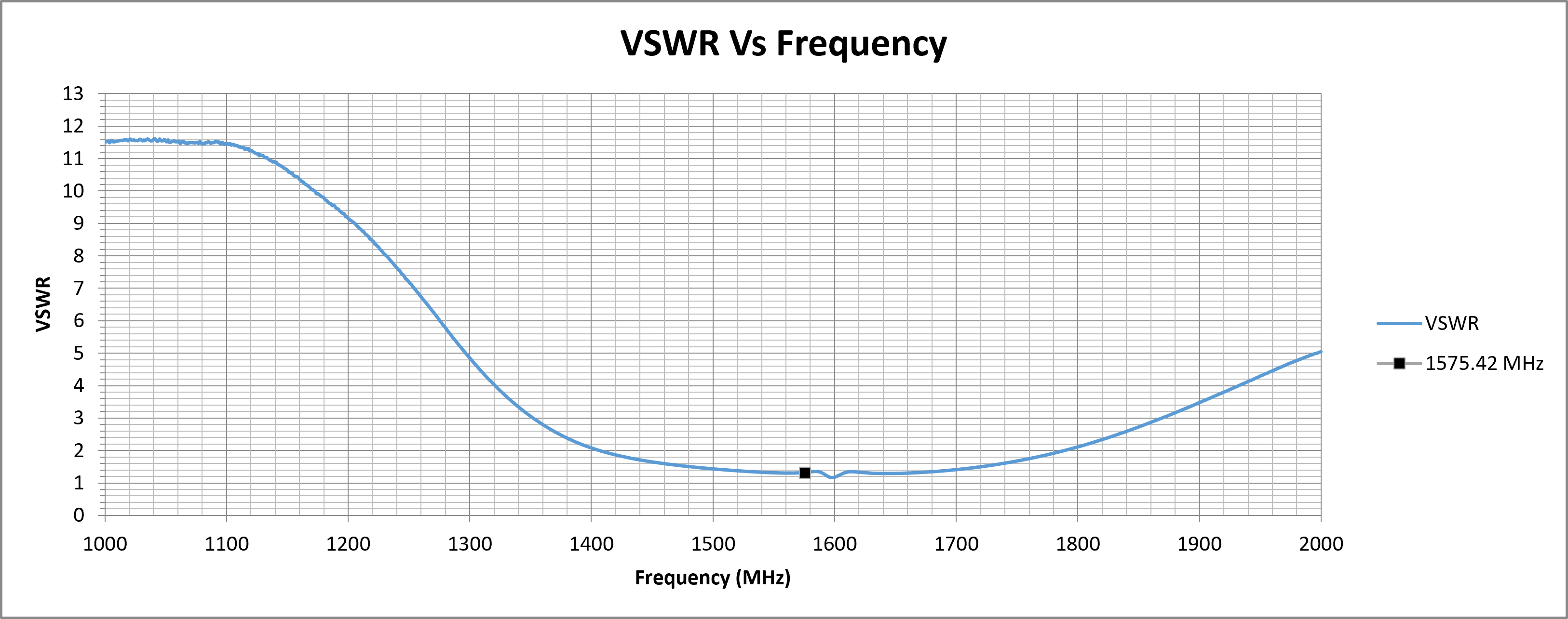
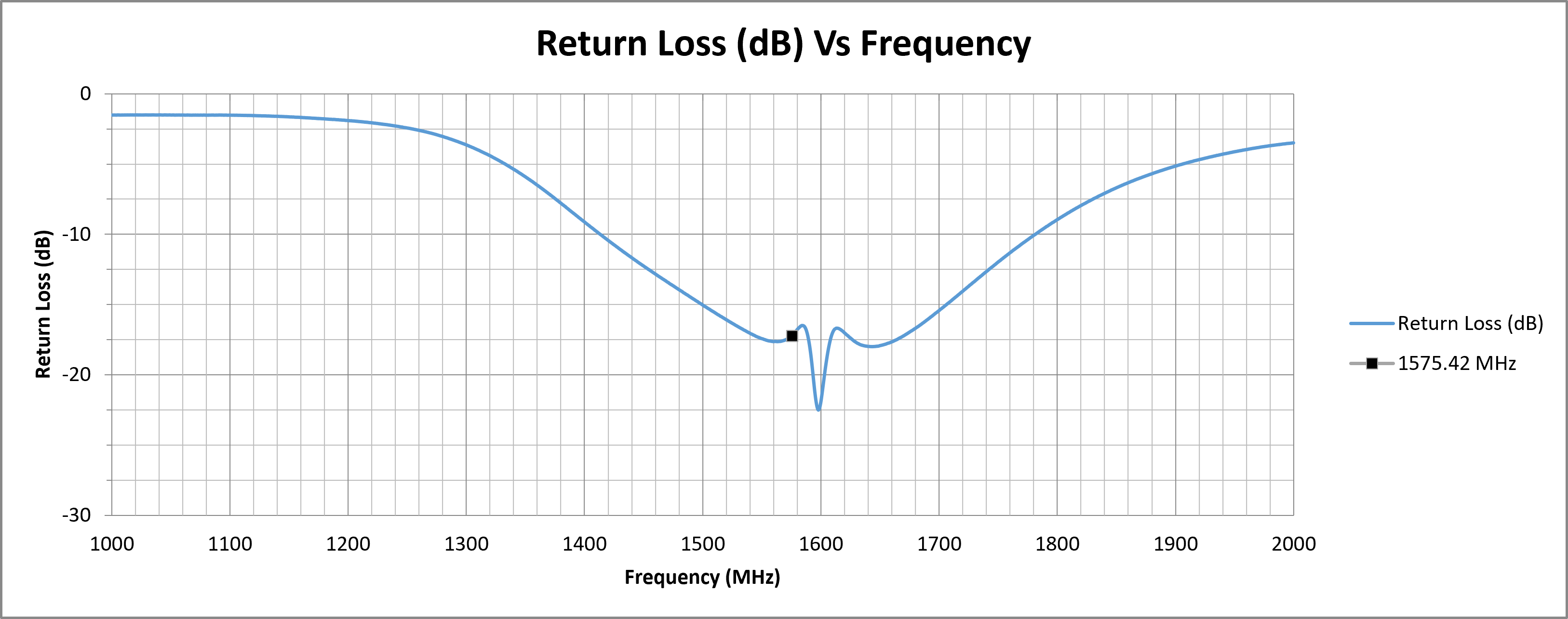
| Return Loss: | -17.21 dB |
| VSWR: | 1.32 |
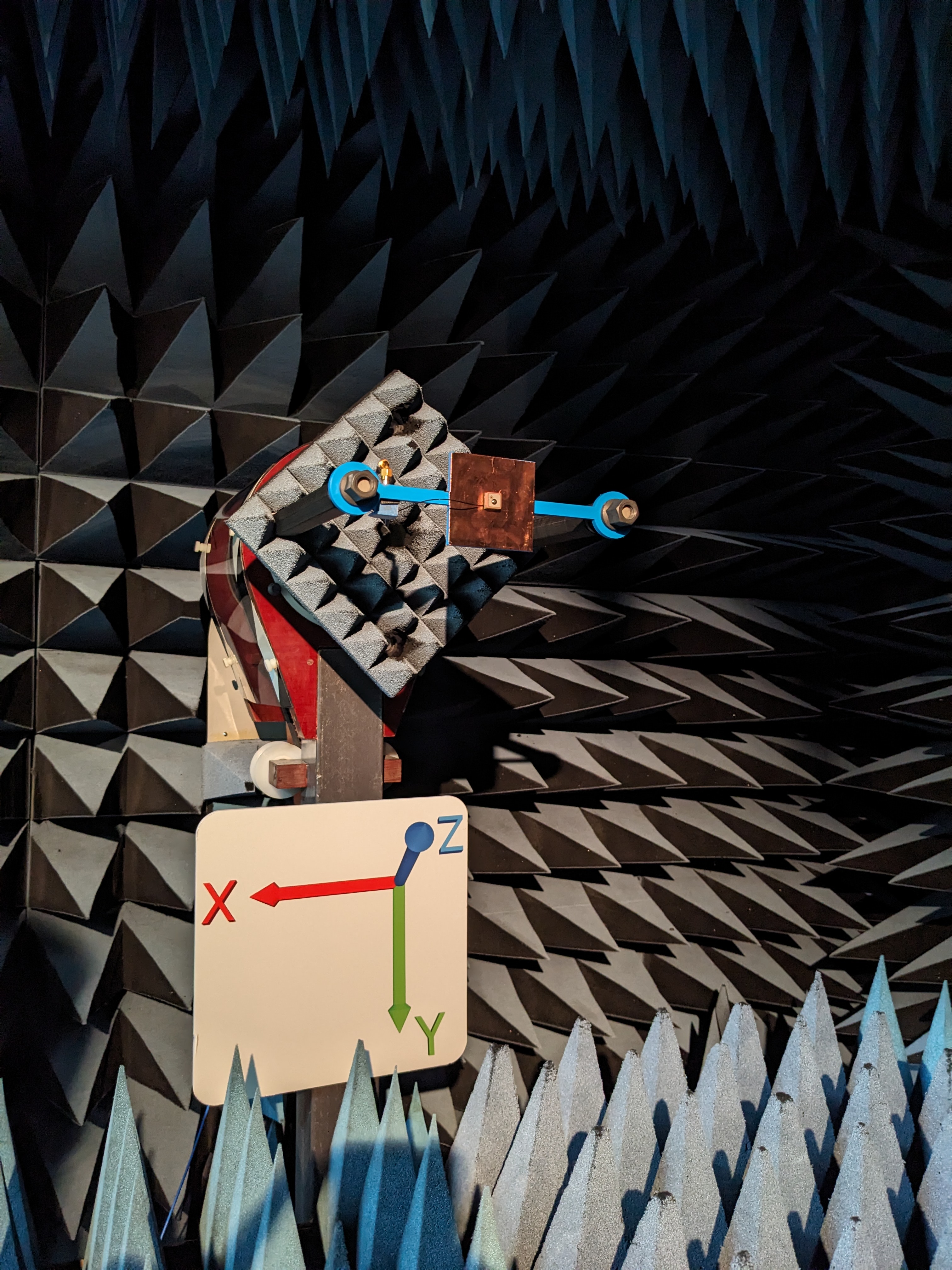
| Required Ground Plane: | 70 x 70 mm |
| Peak RHCP Gain Top Hemisphere: |
14.09 dBiC |
| Supply Voltage: | 3 - 5 V DC |
| Current Consumption: | 5.3 ± 2 mA |
¶ Environmental Specifications
| Operating Temperature range: | -40°C to 80 °C |
| Storage Temperature range: | -40°C to 80°C |
¶ Mechanical Specifications
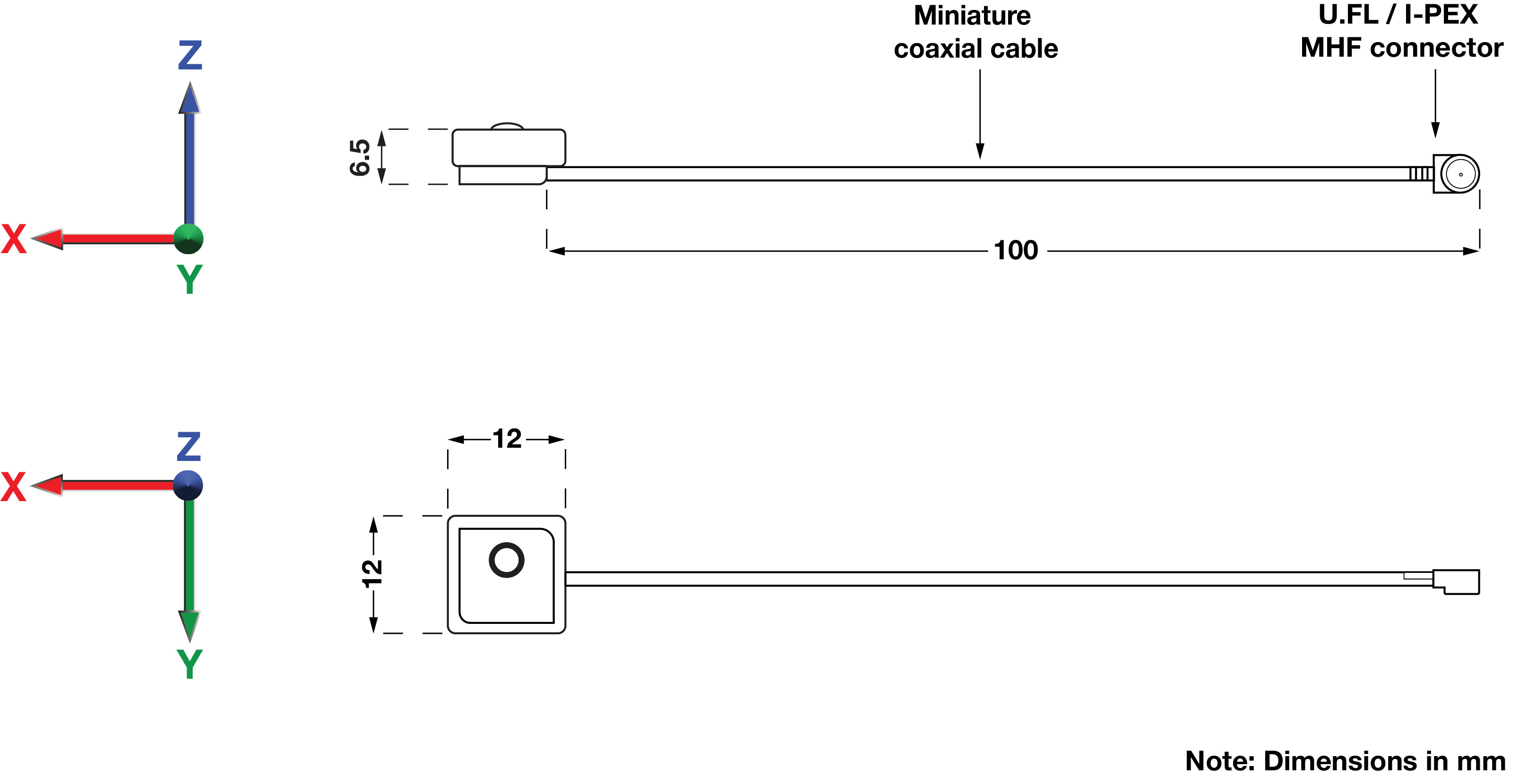
| Dimensions: | L = 12 mm W = 12 mm H = 6.5 mm |
| Weight: | 3.81 g |
| Cable Type: | Miniature Coaxial |
| Cable Length: | 100 mm |
| Connector: | U.FL / I-PEX MHF |
| Mounting method: | Embedded |
¶ Spectrum Coverage*
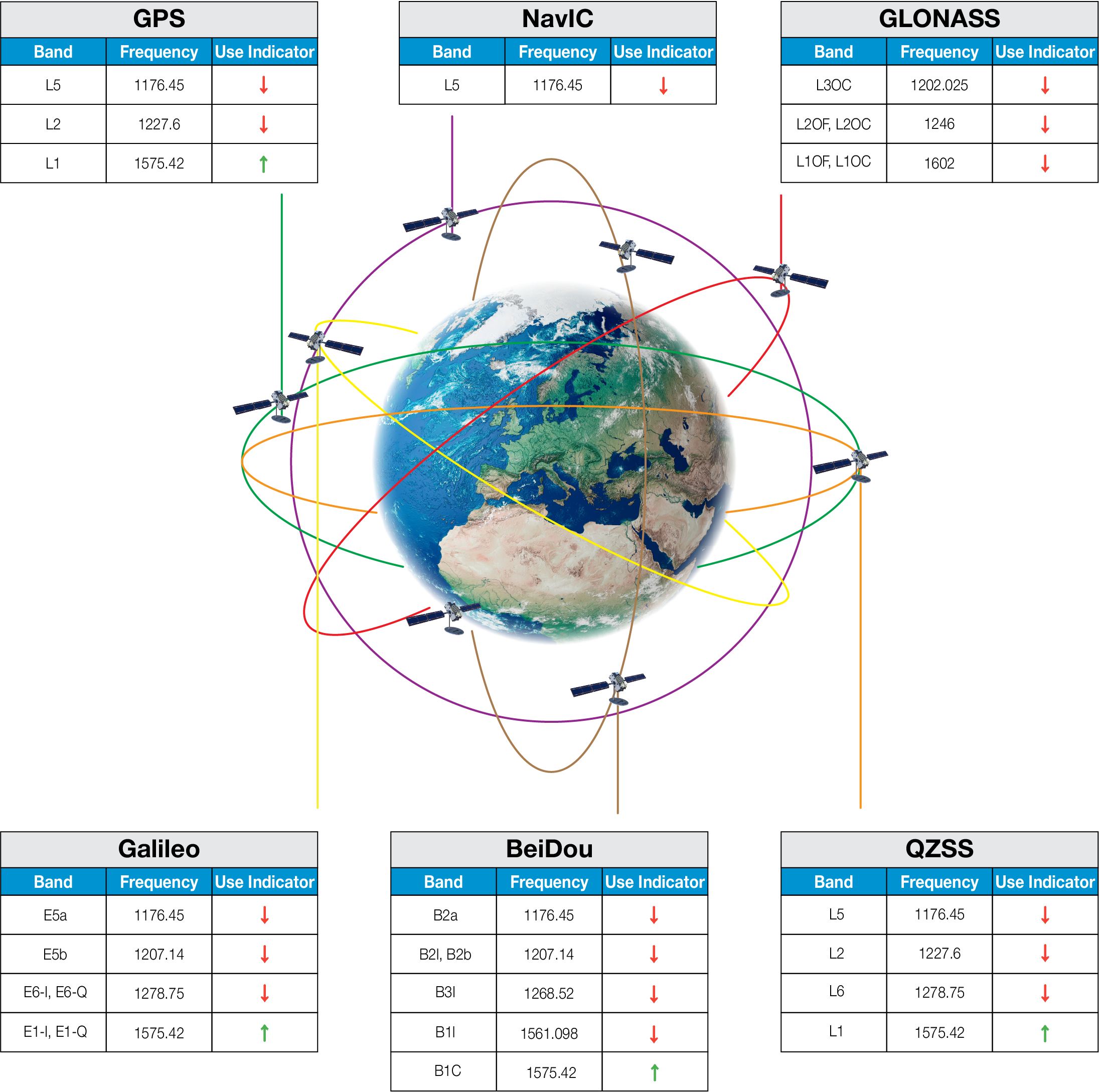
| ↑ Suitable band | □ Adequate band in good signal conditions | ↓ Likely to be unsuitable |
¶ GNSS Standards Band Support
| Electrical Interface | Spherical RF Measurements | |||||
|---|---|---|---|---|---|---|
| Centre Frequency (MHz) | VSWR | Return Loss (dB) | Average RHCP Gain (dBiC) | Peak RHCP Gain (dBiC) | Median Axial Ratio (dB) | Minimum Axial Ratio (dB) |
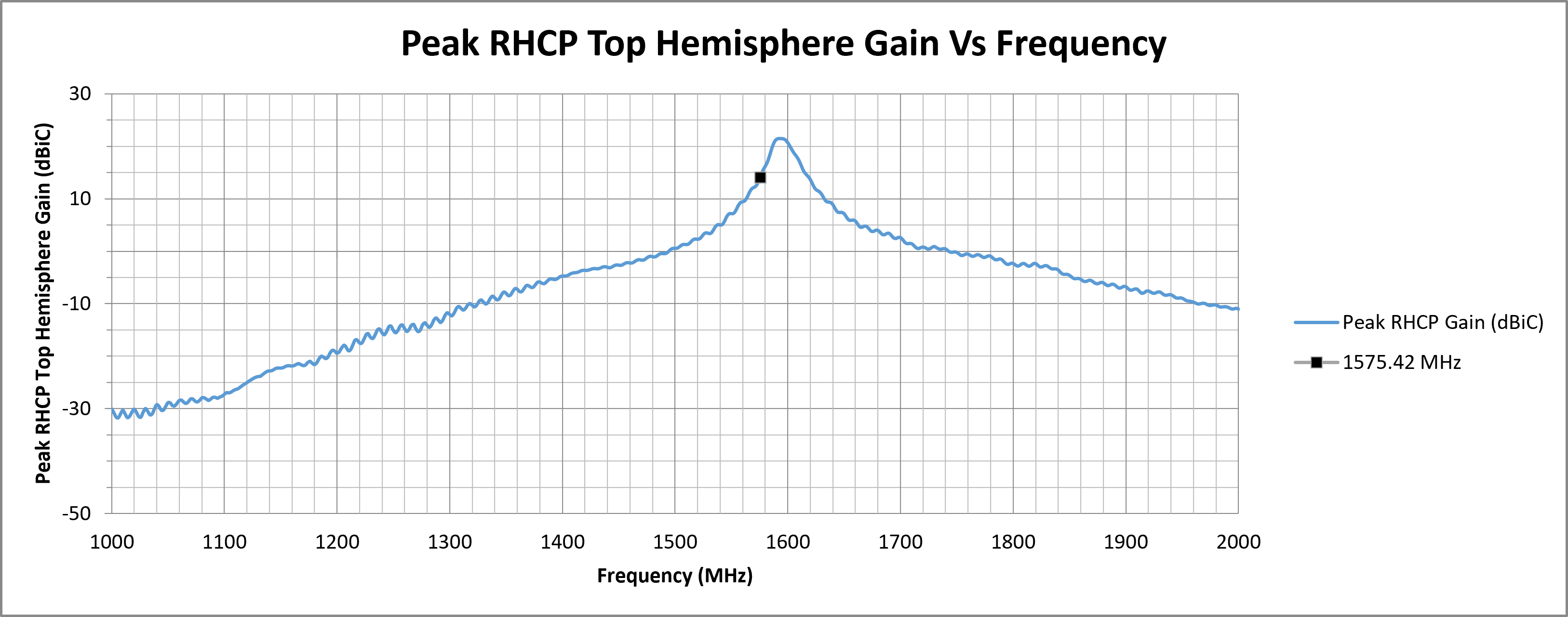
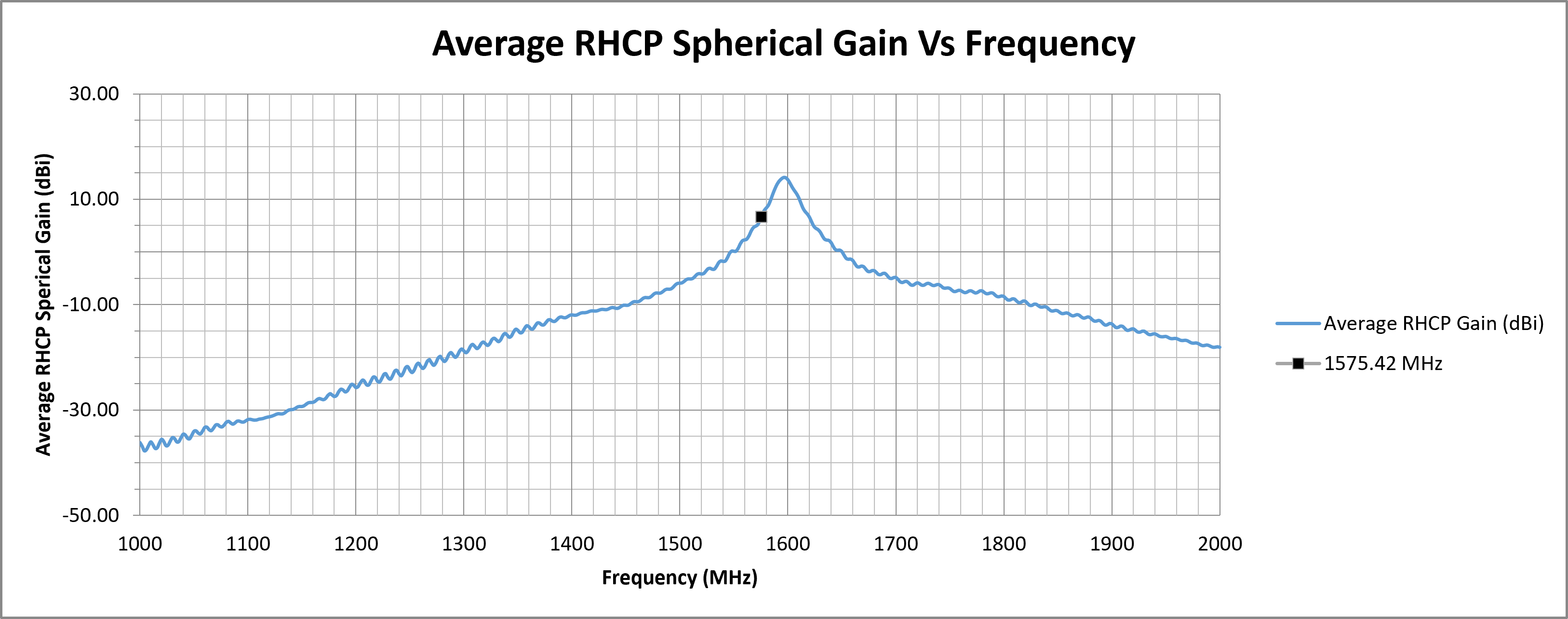
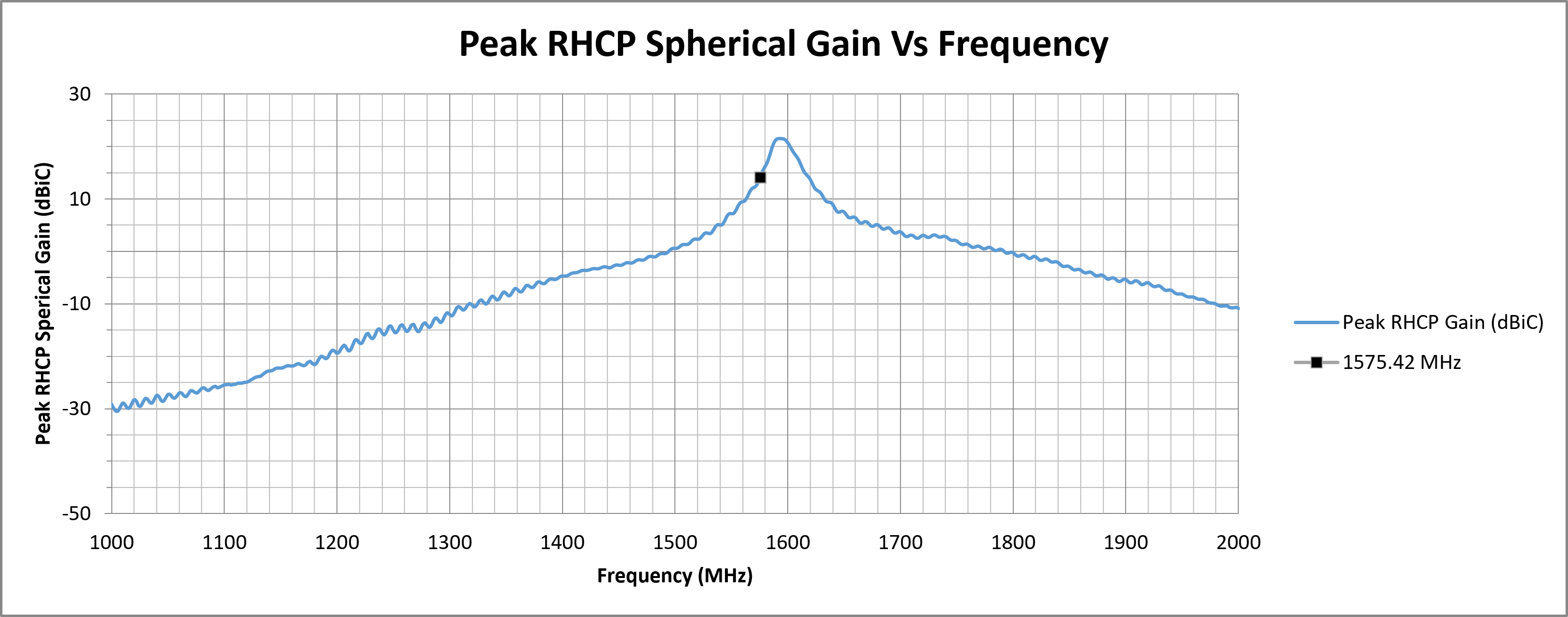
| 1575.42 | 1.3198 | -17.2118 | 6.66 | 14.09 | 19.31 | 1.17 |
| Top Hemisphere RF Measurements | Zenith RF Measurements | |||||
|---|---|---|---|---|---|---|
| Centre Frequency (MHz) | Average RHCP Gain (dBiC) | Peak RHCP Gain (dBiC) | Median Axial Ratio (dB) | Minimum Axial Ratio (dB) | RHCP Gain at Zenith (dBiC) | Axial Ratio at Zenith (dB) |
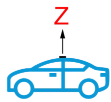
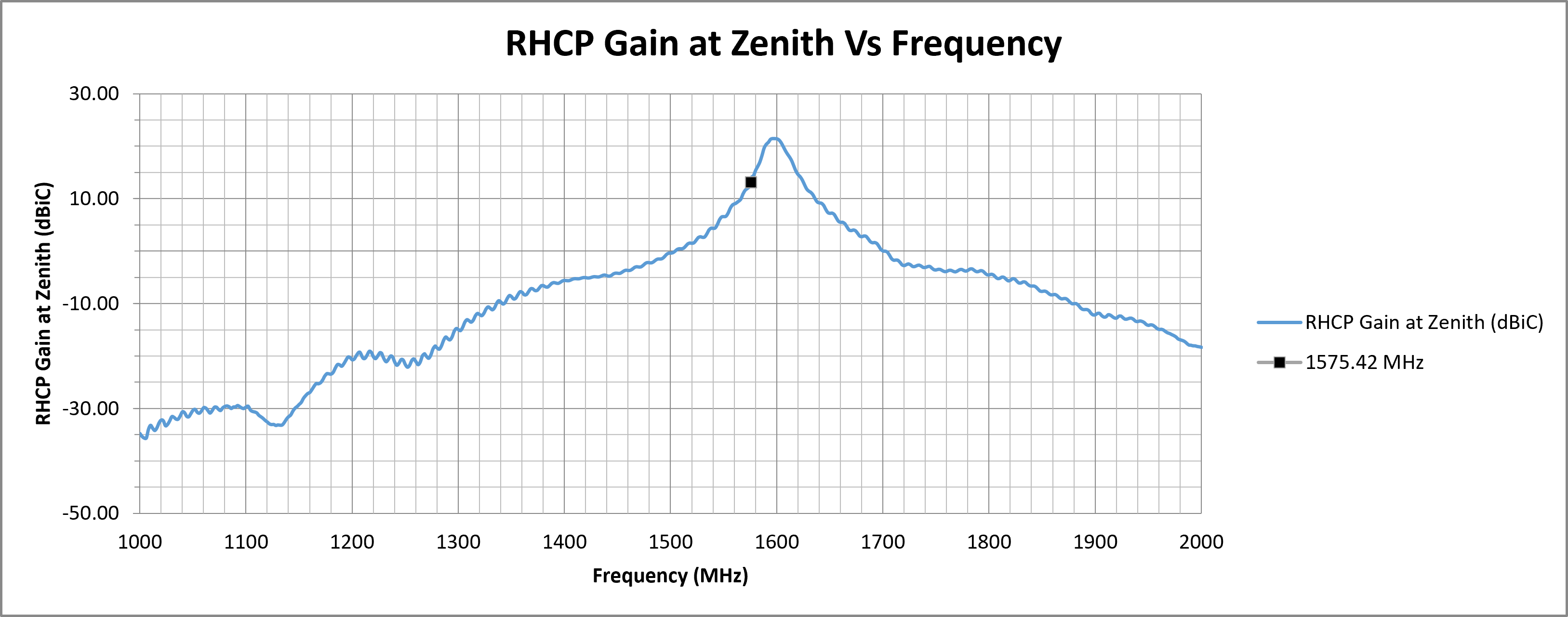
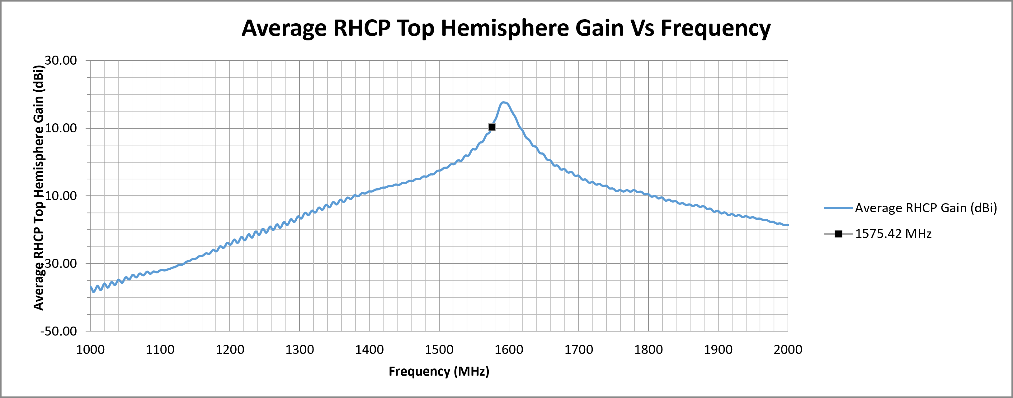
| 1575.42 | 10.38 | 14.09 | 22.87 | 9.95 | 13.19 | 28.29 |
¶ RF Matching Performance
This section illustrates the antenna's impedance matching characteristics across the operating frequency range using VSWR and Return Loss measurements.
¶ RF Zenith
¶ RF Top Hemisphere

¶ RF Spherical
The following graphs display the Average and Peak RHCP Gain across the entire spherical coverage of the antenna. These metrics provide a comprehensive view of the antenna’s ability to receive signals from satellites at all elevations and directions.
Consistently high gain across the sphere ensures strong and stable GNSS reception in a variety of operating conditions.

¶ Test Setup (on 70 x 70 mm Ground Plane)
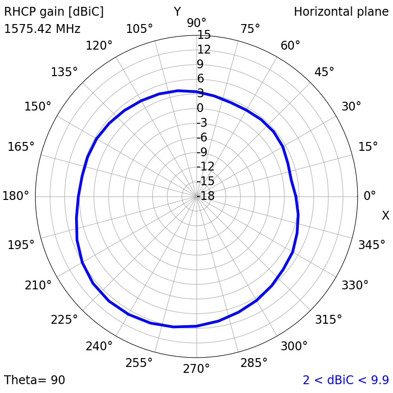
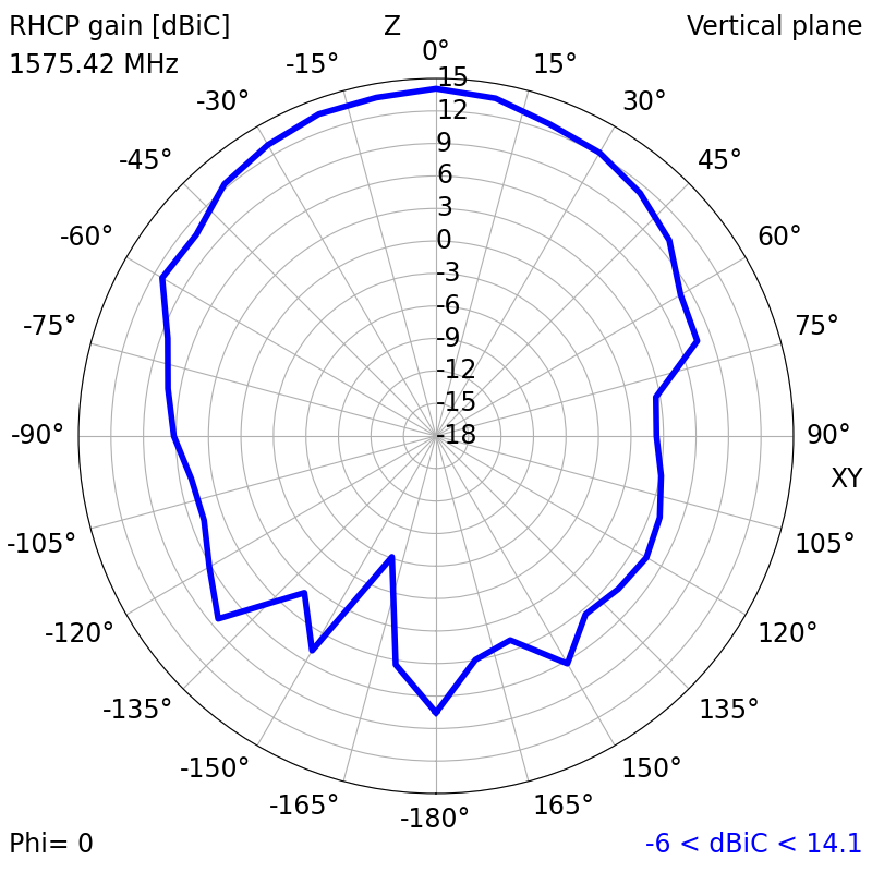
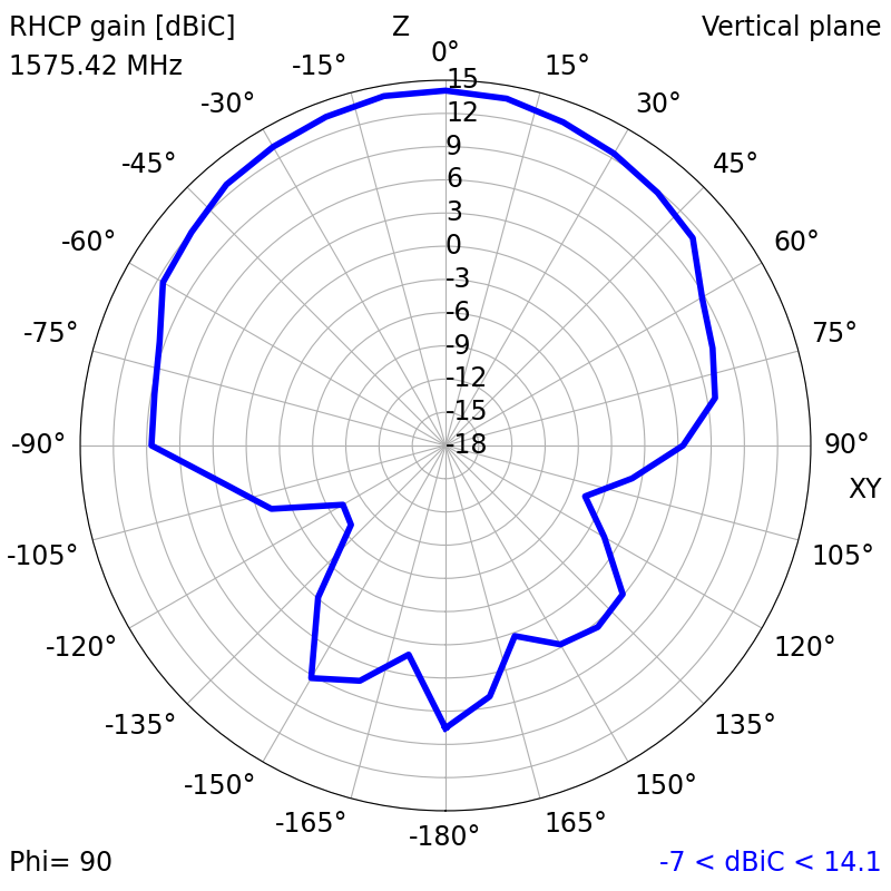
¶ 2D Radiation Plots (1575.42 MHz)
|
|
|
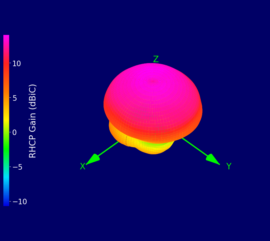
¶ 3D Radiation Plots (1575.42 MHz)
¶ Ordering Details
| Part Number | Description |
|---|---|
| ECHO63/0.1M/UFL/S/S/48 |
12 x 12 mm Active Ceramic Patch GPS L1 Embedded Antenna 0.1 Metre Miniature Coaxial Cable and U.FL / I-PEX MHF I Connector |