Reference Centre
Return to the Antenna Application Notes
Overview
Flexible Printed Circuit (FPC) antennas provide a compact and versatile solution for embedded wireless applications. However, their performance is highly dependent on installation method, positioning and surrounding materials. This guide explains how to achieve the best possible performance when deploying the Siretta ECHO FPC antenna range.
¶ Introduction
Flexible Printed Circuit (FPC) antennas are widely used in:
- LTE devices
- 5G devices
- GNSS receivers
- Bluetooth devices
- WiFi equipment
- IoT products
- Embedded systems
Unlike external antennas, FPC antennas are mounted inside the enclosure and rely heavily on their surrounding environment for optimum performance.
Correct installation is therefore critical.
¶ What is an FPC Antenna?
An FPC antenna consists of:
- a flexible substrate
- a radiating element
- an adhesive mounting surface
- an RF cable assembly
- an RF connector
The flexible construction allows the antenna to be mounted inside an enclosure whilst maintaining good RF performance.
¶ Understanding Antenna Polarisation
One of the most important concepts when installing any antenna is polarisation.
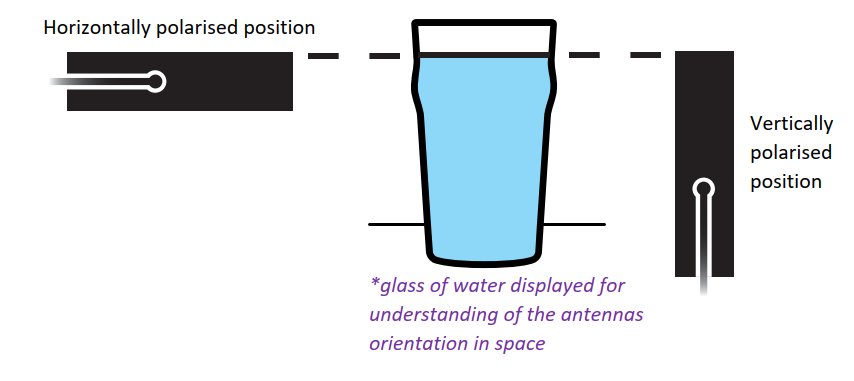
Polarisation describes the orientation of the electromagnetic field radiated by the antenna.
Common polarisations include:
- vertical
- horizontal
- circular
Matching antenna polarisation improves signal transfer and communication efficiency.
¶ FPC Antenna Installation Basics
Unlike traditional external antennas, FPC antennas rely on careful positioning within the host enclosure.
The antenna should be positioned:
- away from metal structures
- away from batteries
- away from displays
- away from large ground planes
- away from noisy electronics
The aim is to provide the antenna with the clearest possible RF environment.
¶ Recommended Installation Position
The following example illustrates a recommended installation arrangement.
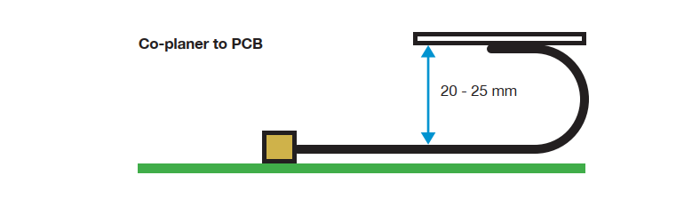
The antenna should be located towards the edge of the enclosure wherever possible.
This allows the radiating element to operate with minimal obstruction.
¶ Avoid Tight Cable Routing
The RF cable should be routed carefully.
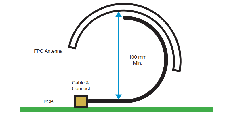
Avoid:
- tight cable loops
- sharp bends
- cable crushing
- excessive strain
Poor cable routing can negatively affect RF performance and long-term reliability.
¶ Correct Cable Bend Radius
Maintaining a suitable cable bend radius is essential.
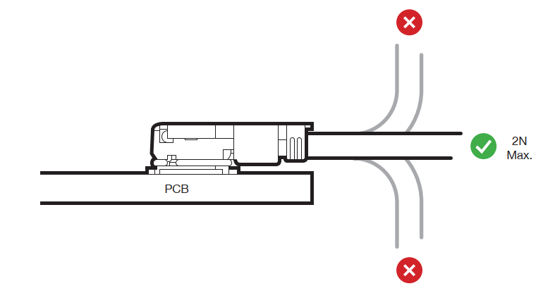
Excessive bending may:
- damage the cable
- alter cable impedance
- reduce antenna performance
- shorten cable life
Best Practice
Use smooth cable bends and avoid forcing the cable into tight spaces.
¶ Correct Antenna Placement
The antenna should be mounted on a suitable non-metallic surface.
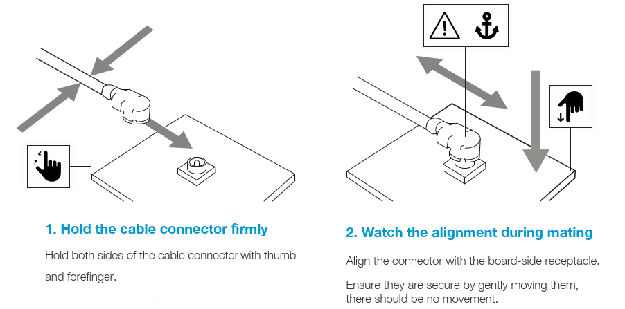
Suitable mounting materials include:
- ABS plastic
- polycarbonate
- acrylic
- composite materials
Metal mounting surfaces should be avoided unless specifically designed into the antenna system.
¶ Incorrect Installation Examples
The following examples show installation methods that should be avoided.
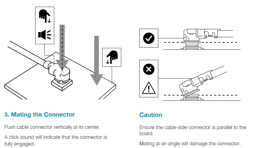
Poor installation practices may result in:
- reduced signal strength
- reduced throughput
- increased retransmissions
- poor GNSS reception
- reduced battery life
¶ Mounting Using Adhesive Backing
Most FPC antennas include an adhesive mounting layer.
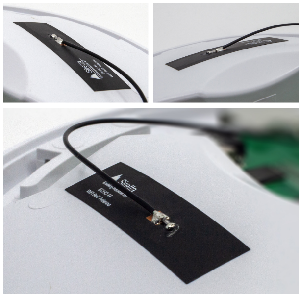
Before mounting:
- Clean the mounting surface.
- Remove contaminants.
- Remove the protective backing.
- Apply firm pressure.
- Avoid repositioning once installed.
Proper adhesion helps ensure long-term reliability.
¶ Ground Plane Considerations
The relationship between the antenna and the ground plane has a major impact on performance.
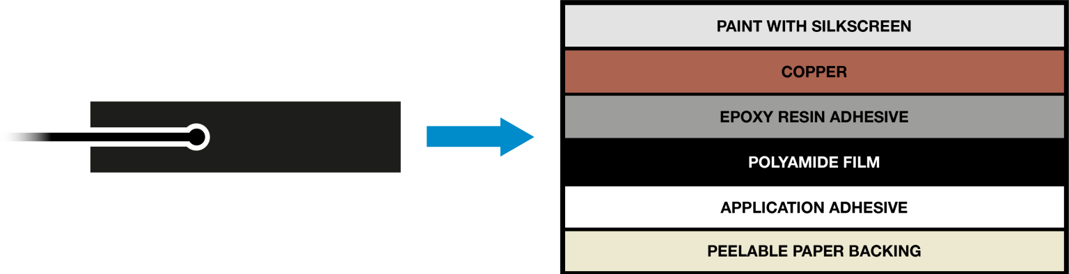
Ground planes influence:
- antenna efficiency
- bandwidth
- radiation pattern
- impedance matching
The optimum arrangement depends on the specific antenna design and application.
¶ Common Installation Mistakes
| Mistake | Potential Impact |
|---|---|
| Mounting on metal | Reduced efficiency and detuning |
| Placing near batteries | Reduced signal strength |
| Tight cable bends | Reduced cable life and performance |
| Installing near displays | Potential RF interference |
| Poor adhesive preparation | Mechanical failure |
¶ Cellular Applications
For LTE, LTE-M, NB-IoT and 5G applications:
- maximise separation from metal
- avoid shielding the antenna
- position near the enclosure edge
- avoid noisy electronics
This helps maximise:
- signal strength
- throughput
- network reliability
¶ GNSS Applications
For GNSS applications:
- maximise sky visibility
- avoid nearby RF emitters
- minimise obstruction
- maintain good separation from cellular antennas
This helps improve:
- satellite acquisition
- tracking stability
- location accuracy
¶ WiFi and Bluetooth Applications
For WiFi and Bluetooth systems:
- avoid enclosure shielding
- maintain antenna clearance
- separate multiple antennas where possible
This improves:
- throughput
- range
- coexistence performance
¶ Installation Checklist
| Check | Status |
|---|---|
| Mounted on non-metallic surface | ✓ |
| Away from batteries | ✓ |
| Away from displays | ✓ |
| Correct cable routing | ✓ |
| Adhesive correctly applied | ✓ |
| Adequate ground plane consideration | ✓ |
¶ Key Takeaways
| Recommendation | Reason |
|---|---|
| Mount away from metal | Prevents detuning and signal loss |
| Use correct cable routing | Maintains RF performance |
| Maintain bend radius | Protects cable integrity |
| Use suitable mounting surfaces | Improves antenna efficiency |
| Consider ground plane effects | Optimises radiation performance |
| Follow installation guidance | Maximises system performance |
¶ Related Documents
- Successful Antenna Selection in Embedded IoT Applications
- Low Profile Antennas in IoT Applications
- GNSS Antenna Selection for Embedded Applications
- Improving Cellular Signal Reception in IoT Applications
Reference Centre
Return to the Antenna Application Notes