Overview
This reference guide explains how radio signals behave inside tunnels, mines, underground caves, service ducts, road tunnels, rail tunnels and other long narrow underground structures.It focuses specifically on the antenna and propagation challenges created by confined spaces, including multipath reflection, polarization instability, waveguide effects, corner loss, obstruction loss and repeater placement.
The guide explains why circularly polarized antennas can provide more stable communication in long reflective channels than conventional linear antennas, and how coverage distance can be improved using repeaters, leaky feeder systems, distributed antennas and careful antenna positioning.
¶ Applicable Products
| Product Type | Description |
|---|---|
| Industrial LTE / 5G Antennas | Antennas used with routers, gateways, modems and telemetry systems installed near tunnel entrances, underground nodes or repeater points. |
| Directional Antennas | Antennas used to project RF energy along a tunnel, corridor, shaft or service passage. |
| Circularly Polarized Antennas | Antennas designed to improve reliability in reflective, obstructed or polarization-variable environments. |
| Embedded IoT Antennas | Compact antennas used inside underground sensors, tracking devices, monitoring equipment and industrial gateways. |
| Cellular Routers and Modems | Communication equipment used to backhaul underground systems to LTE, 5G, Ethernet, fibre or private network infrastructure. |
| RF Survey Equipment | Tools used to measure signal strength, coverage distance, cellular availability and antenna placement performance. |
¶ Objectives
This guide explains:
- Why tunnels, mines and caves behave differently from open-air environments.
- Why long narrow spaces can act like imperfect RF waveguides.
- How reflections from walls, floors, ceilings, vehicles, rock, water and metalwork affect antenna performance.
- Why linear polarization can become unreliable in underground channels.
- Why circular polarization can improve link stability in reflective tunnels.
- Why circular polarization is not a replacement for good RF design.
- How repeaters, leaky feeders and distributed antenna systems improve coverage distance.
- How antenna placement, height, spacing and orientation affect real-world performance.
- How to design more reliable underground RF links.
Expected Result
At the end of this guide, the reader should understand why antenna selection and placement are critical in tunnels and underground environments, and how circular polarization, repeaters and distributed design techniques can be used to improve communication distance and reliability.
¶ Why Underground RF Propagation Is Difficult
Radio waves normally propagate most predictably in open space where there is a clear line of sight between the transmitting and receiving antennas.
Underground environments are very different.
A tunnel or mine gallery is usually:
- Long.
- Narrow.
- Irregular.
- Reflective.
- Partially obstructed.
- Moist or wet.
- Surrounded by rock, soil, concrete or metal reinforcement.
- Filled with machinery, pipes, cables, vehicles and personnel.
This creates a highly complex RF environment.
Instead of a single clean signal travelling from transmitter to receiver, the receiver may see many delayed versions of the same signal arriving from different directions.
These delayed copies are caused by reflections from:
- Tunnel walls.
- Floors.
- Roofs.
- Rock faces.
- Support mesh.
- Metal rails.
- Vehicles.
- Pipes.
- Cable trays.
- Water.
- Machinery.
- Doorways and side passages.
These reflected signals are known as multipath.
Multipath can cause:
- Deep fading.
- Rapid signal variation.
- Reduced data throughput.
- Poor modem stability.
- Packet loss.
- Increased retransmissions.
- Reduced usable range.
- Unreliable roaming between nodes.
- Positioning and tracking errors.
In tunnels, mines and underground caves, the RF path is therefore not only controlled by distance. It is also controlled by reflections, polarization behaviour, tunnel shape, wall material, bends, obstructions and antenna placement.
¶ Tunnels as RF Waveguides
A tunnel can behave like a very large, imperfect waveguide.
In free space, RF energy expands outward in all directions.
Inside a tunnel, some of that energy is contained by the surrounding walls, roof and floor.
This means that the tunnel can guide radio energy along its length.
¶ Figure 1 - Tunnels as Waveguides
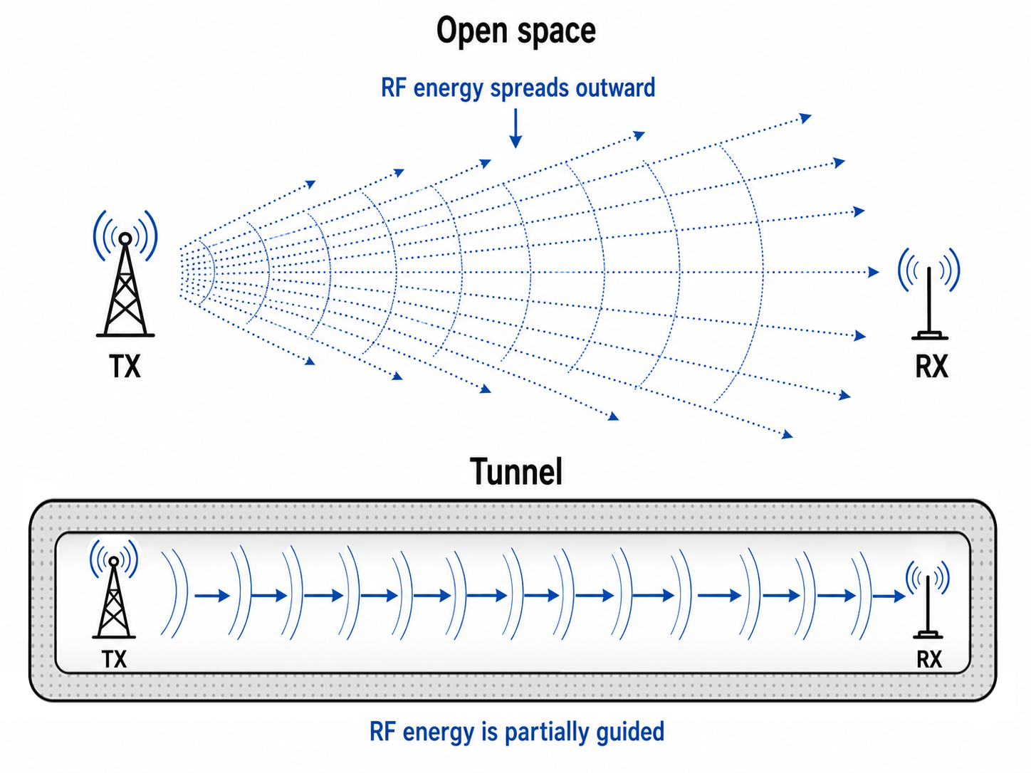
This waveguide effect can be helpful because it may allow signals to travel further along a straight tunnel than expected.
However, it can also be harmful because the signal no longer behaves like a simple free-space path.
Tunnel propagation depends on:
- Tunnel width.
- Tunnel height.
- Tunnel shape.
- Wall material.
- Wall roughness.
- Moisture.
- Frequency.
- Antenna position.
- Antenna height.
- Antenna polarization.
- Obstructions.
- Side tunnels.
- Corners and bends.
Important Note
A tunnel may guide RF energy along a straight section, but this does not mean coverage will automatically be reliable. Small changes in antenna position, polarization, tunnel shape or obstruction layout can create large changes in received signal strength.
¶ Linear Polarization in Tunnels
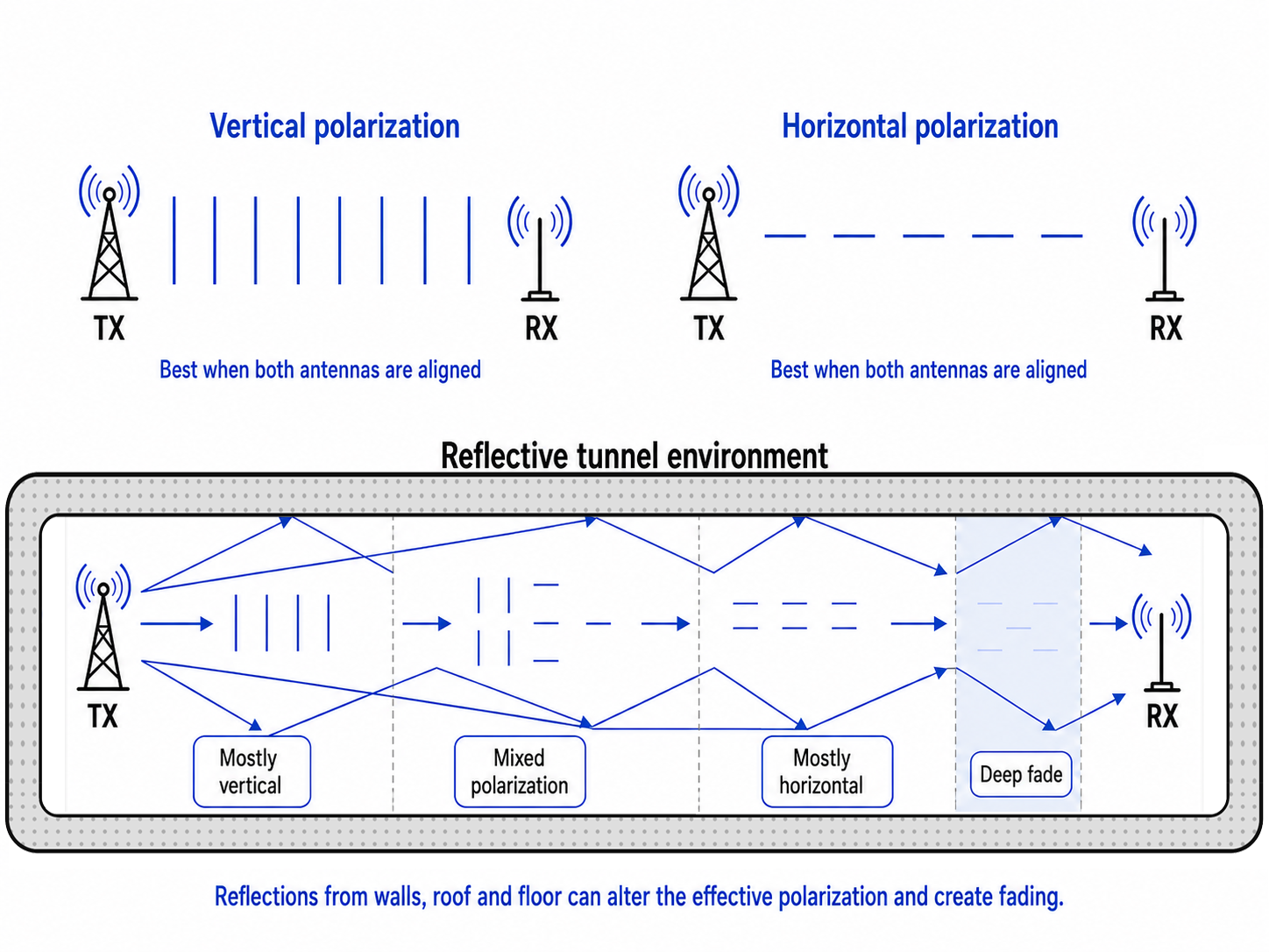
Most terrestrial cellular, Wi-Fi and industrial antennas are linearly polarized.
A linearly polarized antenna transmits an electric field in a fixed plane.
The two most common forms are:
- Vertical polarization.
- Horizontal polarization.
¶ Figure 2 - Polarization in Tunnels
In open-air installations, linear polarization is often effective because the antenna orientation can usually be controlled.
For example:
- A vertically polarized antenna communicates efficiently with another vertically polarized antenna.
- A horizontally polarized antenna communicates efficiently with another horizontally polarized antenna.
- A 90° mismatch between two linear antennas can produce significant cross-polarization loss.
In tunnels, this becomes much more difficult.
A signal that starts vertically polarized may not remain vertically dominant after travelling down the tunnel.
The signal can reflect from the walls, roof and floor many times.
Each reflection can alter the phase, amplitude and effective polarization of the received signal.
As a result, a receiver may see:
- Mostly vertical energy at one point.
- Mostly horizontal energy a few metres later.
- A mixture of vertical and horizontal energy elsewhere.
- A deep fade where reflected signals cancel the wanted signal.
This makes linear polarization unpredictable in long reflective channels.
¶ Why Linear Polarization Can Work Badly Underground
Linear antennas can work well in some tunnel sections, especially where the geometry, frequency and antenna placement happen to favour that polarization.
However, the problem is consistency.
A vertically polarized antenna may perform well at one location and badly at another.
A horizontally polarized antenna may perform badly near the transmitter, then better further along the tunnel.
This happens because the tunnel environment continually changes the signal.
¶ Figure 3 - Polarization Problems in Tunnels
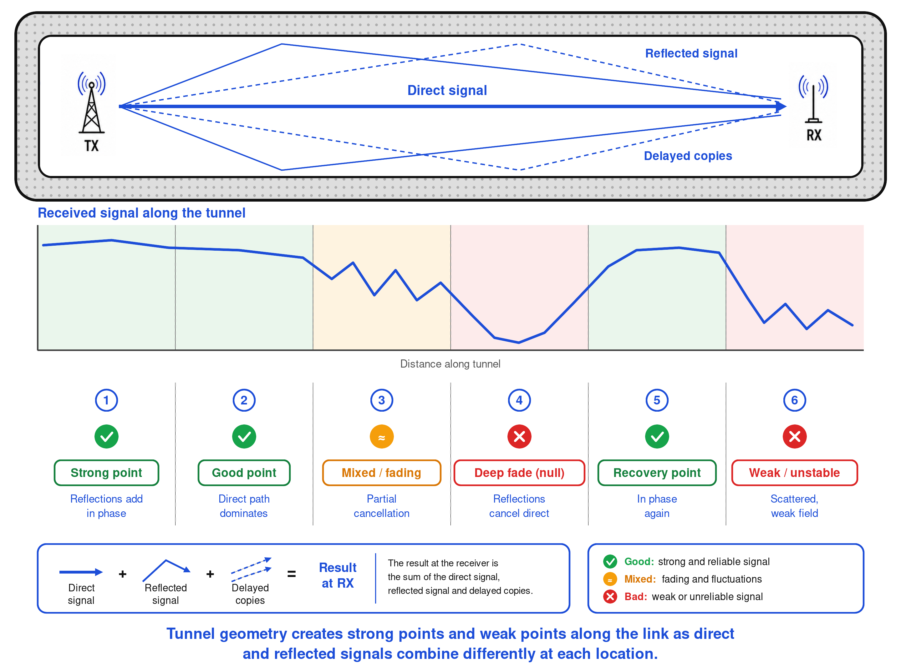
Common linear polarization problems include:
| Problem | Effect |
|---|---|
| Polarization mismatch | The receive antenna is not aligned with the dominant arriving field. |
| Multipath fading | Direct and reflected signals add or cancel depending on phase. |
| Standing-wave effects | Strong and weak signal zones occur along the tunnel. |
| Orientation sensitivity | Small rotations of the antenna or device can change signal strength. |
| Obstruction sensitivity | Vehicles, machinery or people may block or reshape the RF path. |
| Corner loss | RF energy can reduce sharply around bends and junctions. |
The result is often a tunnel link that appears strong in one place, unstable in another, and completely unusable at certain points.
¶ Circular Polarization in Tunnels
Circular polarization behaves differently.
Instead of the electric field remaining fixed in one plane, the field rotates continuously as the wave propagates.
Circular polarization may be:
- Right-Hand Circular Polarization, or RHCP.
- Left-Hand Circular Polarization, or LHCP.
¶ Figure 4 - Circular Polarization in Tunnels
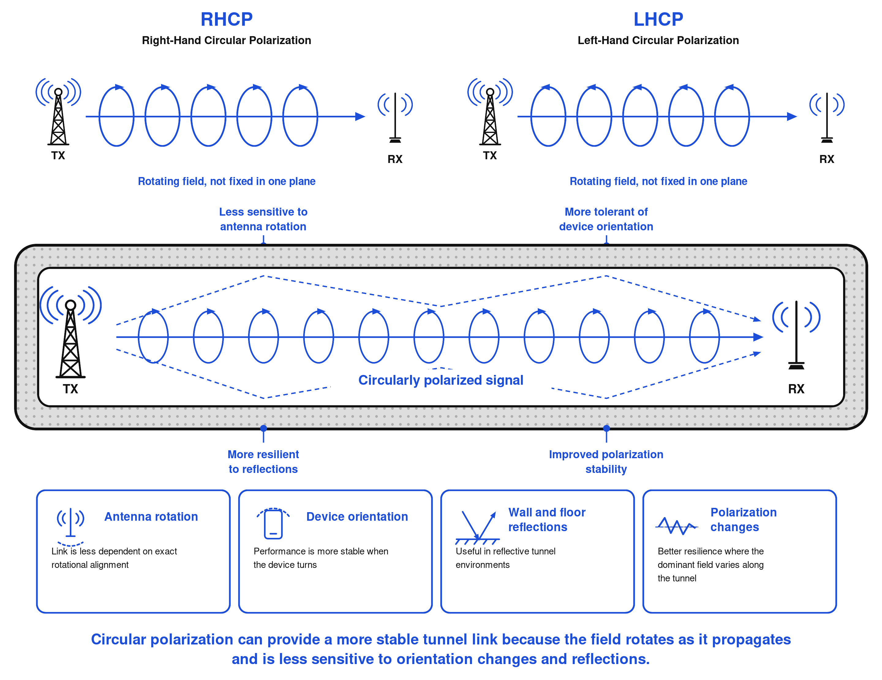
A circularly polarized antenna is less dependent on the precise rotational alignment between the transmitting and receiving antennas.
This is particularly useful in underground environments because the received signal may arrive after multiple reflections and with a changed effective polarization.
Circular polarization can provide a more stable link because it contains both orthogonal linear components with a 90° phase relationship.
In practice, this means that circularly polarized antennas are often more tolerant of:
- Antenna rotation.
- Device orientation.
- Wall reflections.
- Ceiling and floor reflections.
- Polarization changes along the tunnel.
- Machinery and vehicle obstructions.
- Irregular tunnel geometry.
¶ Reflection and Polarization Reversal
One of the most important properties of circular polarization is its behaviour after reflection.
When a circularly polarized signal reflects from a conductive or reflective surface, its handedness reverses.
For example:
| Original Signal | After One Reflection |
|---|---|
| RHCP | LHCP |
| LHCP | RHCP |
This means that a receiver designed for RHCP naturally rejects many single-reflection LHCP components.
Likewise, an LHCP receiver naturally rejects many single-reflection RHCP components.
¶ Figure 5 - Reflections in Tunnels
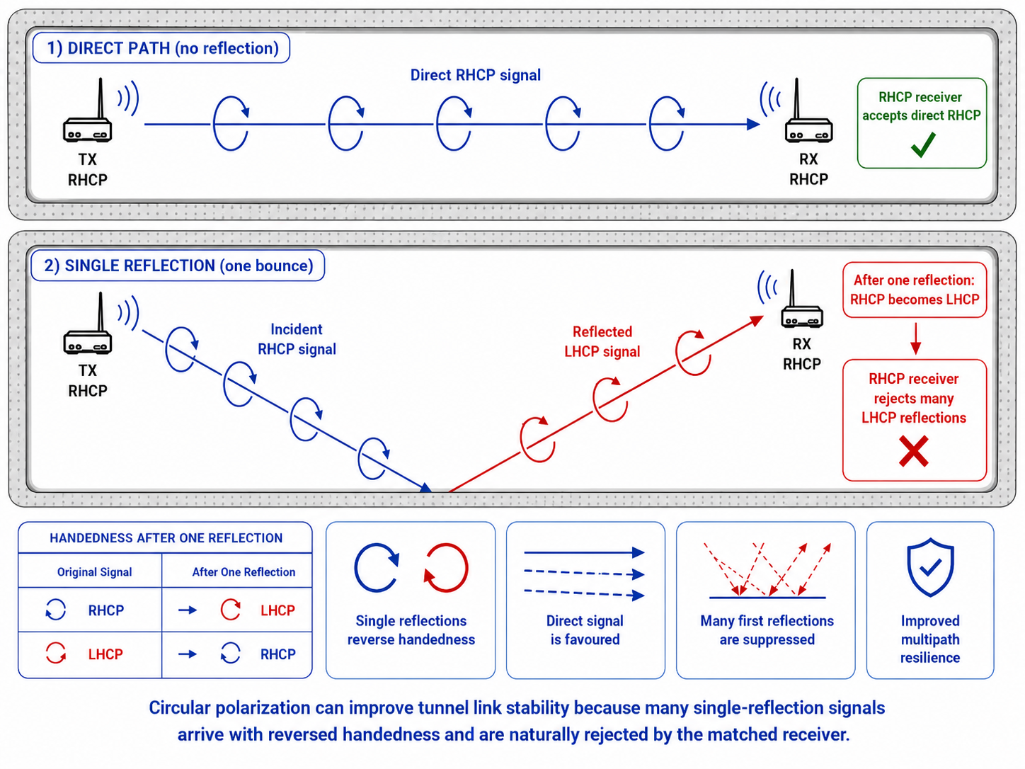
This can reduce the impact of the strongest first reflections, which are often the most damaging multipath components.
For this reason, circular polarization can improve signal stability in tunnels compared with linear polarization, where reflected waves may combine strongly with the direct wave and create large distance-dependent signal variations.
Important Note
Circular polarization does not remove all multipath. After multiple reflections, scattering and depolarization, some reflected energy can still be received. Circular polarization improves resilience, but it does not eliminate the need for good antenna placement and coverage design.
¶ Linear vs Circular Polarization in Long Narrow Channels
| Feature | Linear Polarization | Circular Polarization |
|---|---|---|
| Antenna orientation sensitivity | High | Lower |
| Performance in open line of sight | Good when aligned | Good when matched |
| Performance in reflective tunnels | Can vary significantly | Usually more stable |
| First-reflection behaviour | Reflections can interfere strongly | Single reflections often reverse handedness and are partly rejected |
| Fading behaviour | Deep fades are common | Fading is often reduced |
| Obstruction tolerance | Depends heavily on geometry | Often more resilient |
| Installation tolerance | More sensitive to rotation and alignment | More forgiving |
| Best use case | Controlled installations with predictable geometry | Reflective, changing or obstructed tunnel environments |
¶ Why Circular Polarization Helps in Mines and Caves
Mines and caves are often less predictable than road or rail tunnels.
They may include:
- Irregular rock surfaces.
- Rough walls.
- Uneven floors.
- Sharp bends.
- Slopes.
- Low ceilings.
- Side galleries.
- Wet surfaces.
- Metallic supports.
- Reinforcement mesh.
- Vehicles and heavy machinery.
- Dynamic obstructions.
These features scatter and reflect RF energy in many directions.
A linearly polarized system may become unreliable because the dominant received polarization changes along the route.
Circular polarization helps because it is less dependent on one fixed electric-field orientation.
This makes it particularly useful for:
- Underground mining communications.
- Tunnel telemetry.
- Cave monitoring.
- Emergency communication nodes.
- Underground asset tracking.
- Remote sensors.
- Private LTE / 5G tunnel systems.
- Wi-Fi or industrial IoT coverage in confined passages.
- Vehicle communication in mines and service tunnels.
¶ Straight Tunnel Sections
Straight tunnel sections are usually the easiest underground RF environment to cover.
If the tunnel is reasonably uniform, RF energy may propagate along the tunnel with partial waveguide support.
In this case, antenna choice and placement are critical.
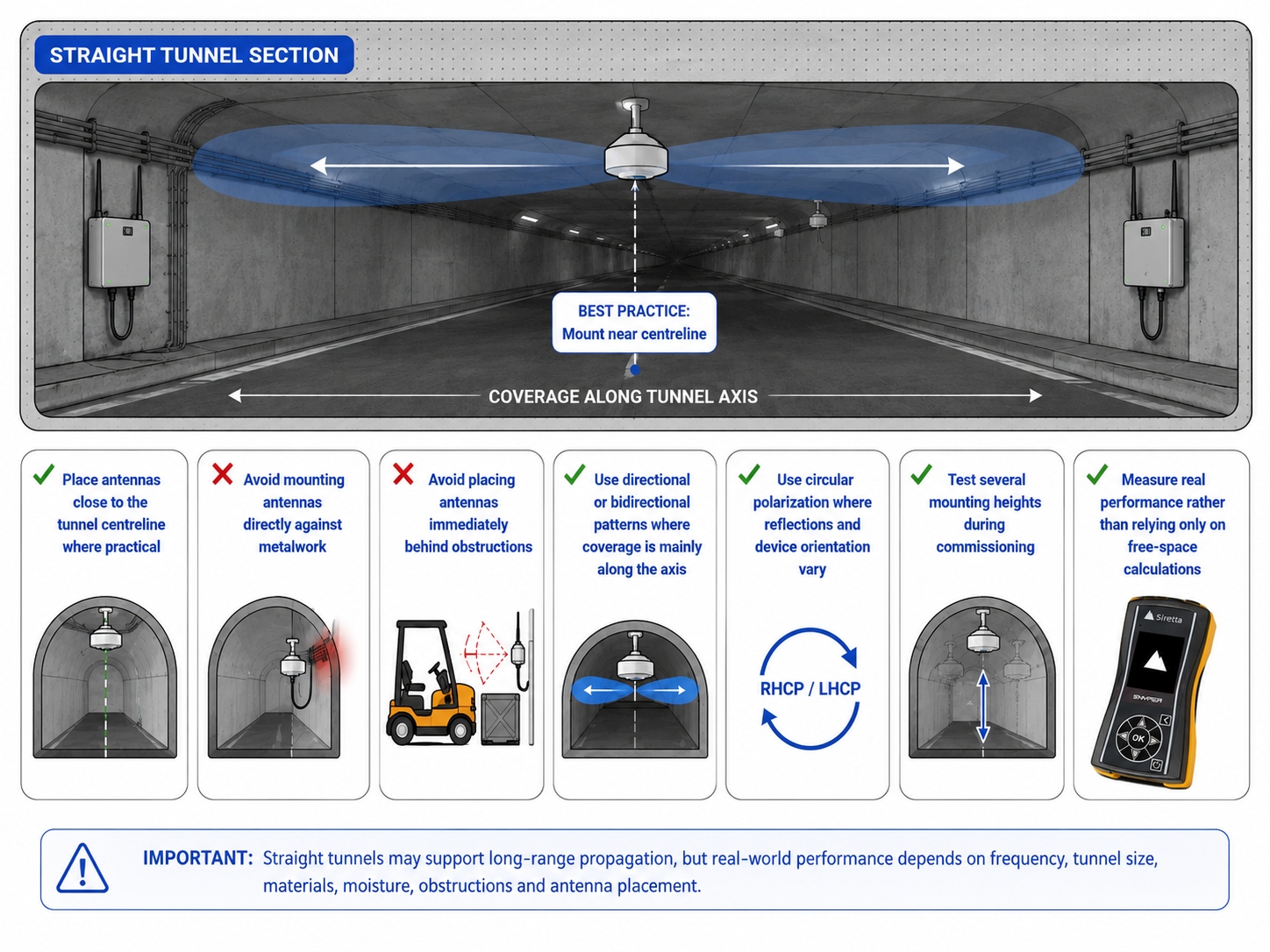
Recommended design principles:
- Place antennas close to the tunnel centreline where practical.
- Avoid mounting antennas directly against metalwork.
- Avoid placing antennas immediately behind obstructions.
- Use directional or bidirectional radiation patterns where coverage is mainly required along the tunnel axis.
- Use circular polarization where reflections and device orientation are expected to vary.
- Test several mounting heights during commissioning.
- Measure real performance rather than relying only on free-space calculations.
¶ Figure 6 - Straight Tunnel Coverage

¶ Bends, Corners and Junctions
Corners are one of the most difficult parts of underground RF design.
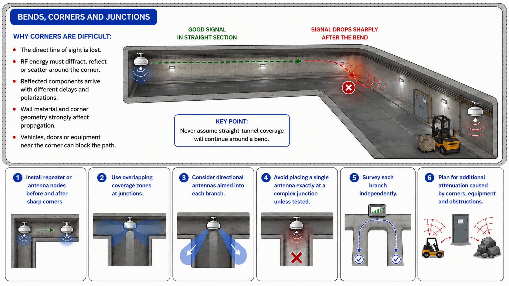
A signal that travels well down a straight tunnel may drop sharply after a bend.
This occurs because:
- The direct line of sight is lost.
- RF energy must diffract, reflect or scatter around the corner.
- Reflected components arrive with different delays and polarizations.
- Wall material and corner geometry strongly affect propagation.
- Vehicles, doors or equipment near the corner can block the path.
¶ Figure 7 - Non Line-Of-Sight Tunnels
Recommended design principles:
- Do not assume straight-tunnel coverage will continue around a bend.
- Install repeater or antenna nodes before and after sharp corners.
- Use overlapping coverage zones at junctions.
- Consider directional antennas aimed into each branch.
- Avoid placing a single antenna exactly at a complex junction unless tested.
- Survey each branch independently.
¶ Obstructions and Moving Equipment
Underground environments often contain large moving or fixed obstructions.
Examples include:
- Mining vehicles.
- Trains.
- Conveyor systems.
- Pumps.
- Cabinets.
- Doors.
- Personnel.
- Cable trays.
- Metallic pipes.
- Reinforced concrete sections.
- Water tanks.
- Temporary works.
These objects can:
- Block the direct signal.
- Create new reflections.
- Change the dominant polarization.
- Cause shadow zones.
- Create sudden fading as machinery moves.
Circular polarization can improve resilience because it is less dependent on a single linear orientation, but physical obstruction still reduces RF energy.
For critical links, coverage should be designed so that there is more than one usable RF path.
¶ Improving Distance with Repeaters
A repeater extends coverage by receiving a signal, amplifying or regenerating it, and retransmitting it further along the tunnel.
Repeaters are useful where:
- The tunnel is too long for a single antenna link.
- There are bends or junctions.
- Obstructions cause shadow zones.
- The required data rate is too high for the available signal level.
- Equipment must operate reliably during movement.
- Emergency coverage is required throughout the route.
¶ Figure 8 - Signal Repeaters
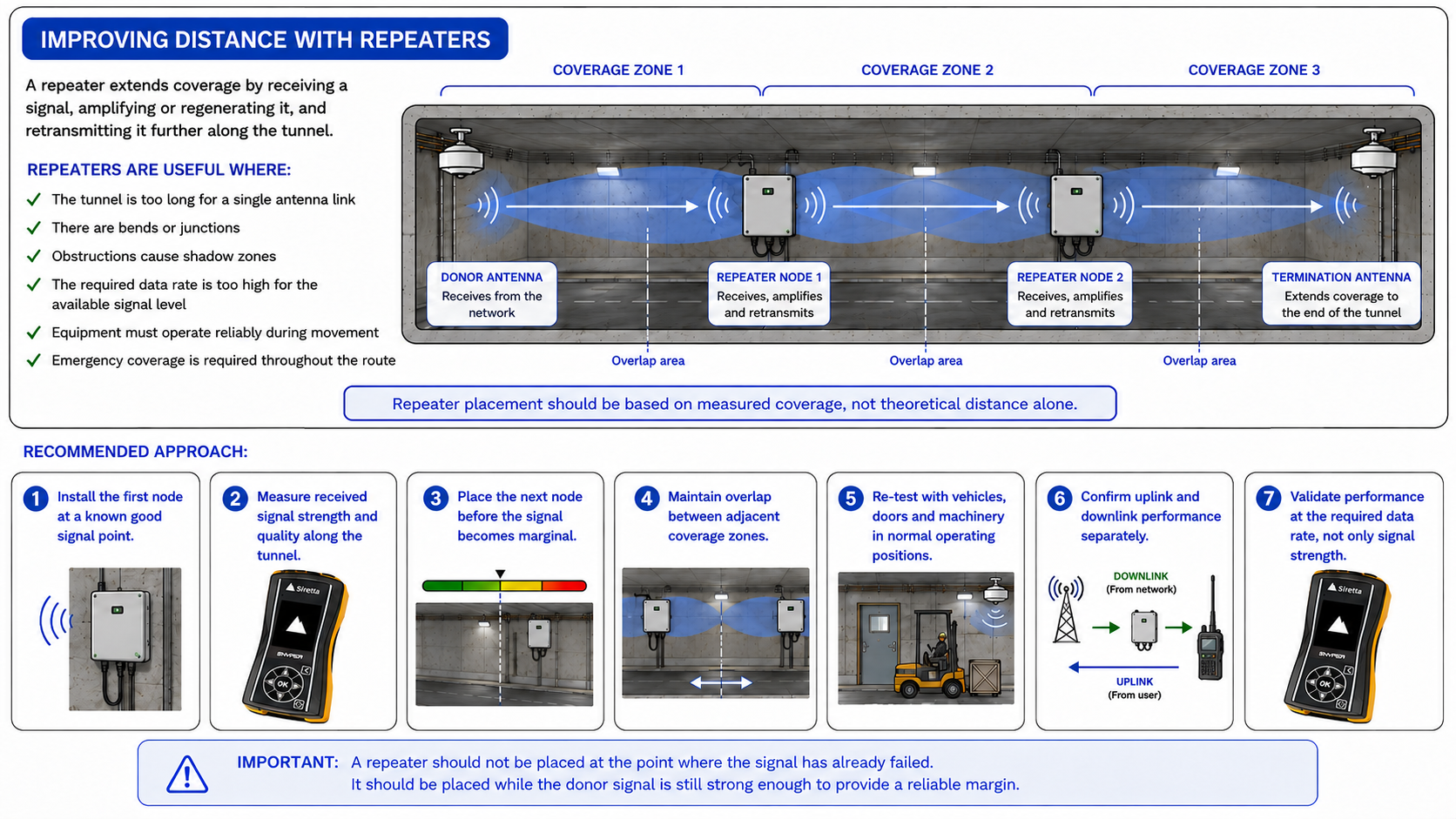
Repeater placement should be based on measured coverage, not theoretical distance alone.
Recommended approach:
- Install the first node at a known good signal point.
- Measure received signal strength and quality along the tunnel.
- Place the next node before the signal becomes marginal.
- Maintain overlap between adjacent coverage zones.
- Re-test with vehicles, doors and machinery in normal operating positions.
- Confirm uplink and downlink performance separately.
- Validate performance at the required data rate, not only signal strength.
Important Note
A repeater should not be placed at the point where the signal has already failed. It should be placed while the donor signal is still strong enough to provide a reliable margin.
¶ Leaky Feeder Systems
A leaky feeder is a special cable installed along a tunnel that deliberately radiates and receives RF energy along its length.
Instead of relying on one antenna to cover a long tunnel, the cable acts like a distributed antenna.
¶ Figure 9 - Leaky Feeder Distribution
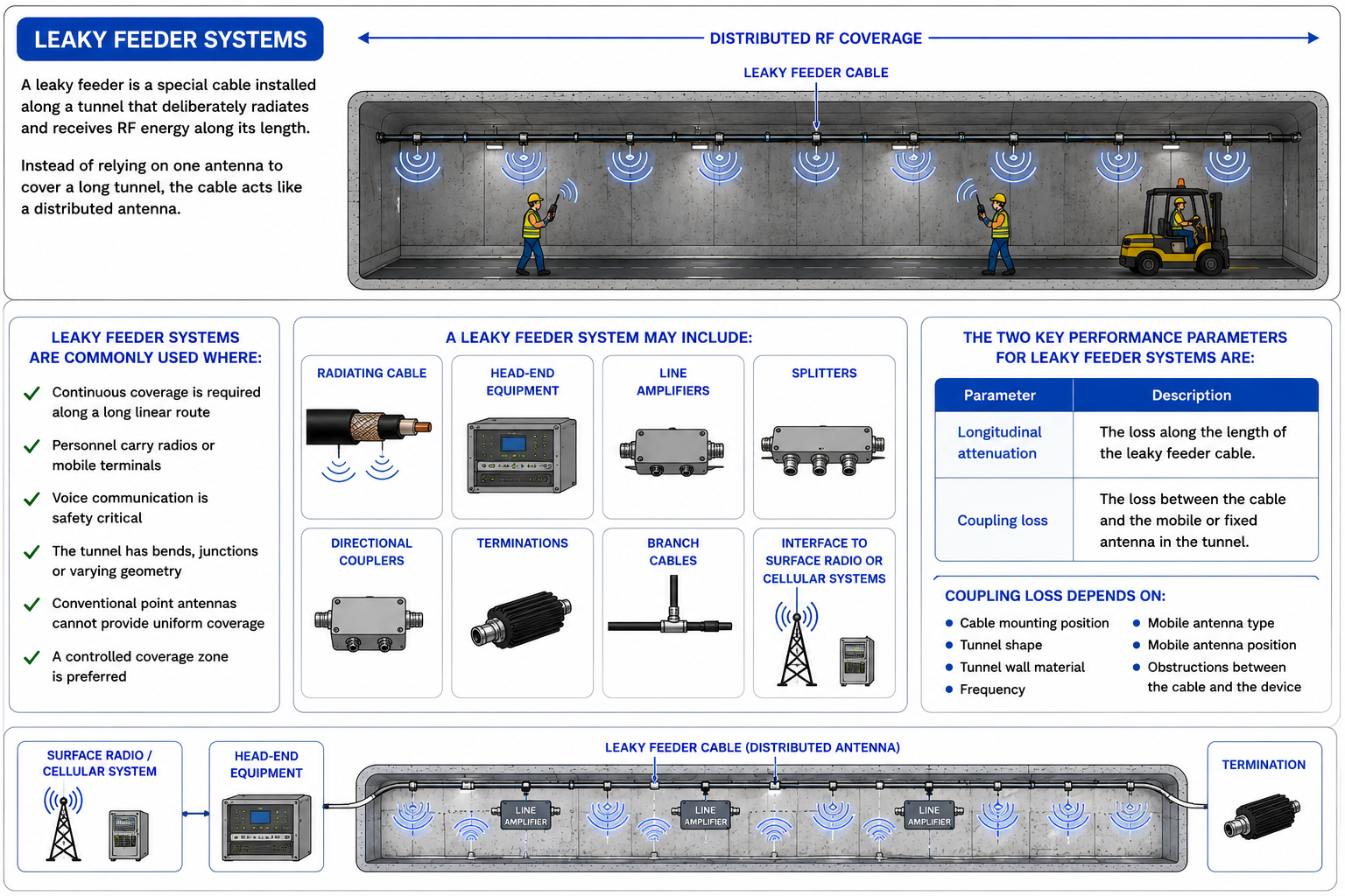
Leaky feeder systems are commonly used where:
- Continuous coverage is required along a long linear route.
- Personnel carry radios or mobile terminals.
- Voice communication is safety critical.
- The tunnel has bends, junctions or varying geometry.
- Conventional point antennas cannot provide uniform coverage.
- A controlled coverage zone is preferred.
A leaky feeder system may include:
- Radiating cable.
- Head-end equipment.
- Line amplifiers.
- Splitters.
- Directional couplers.
- Terminations.
- Branch cables.
- Interface to surface radio or cellular systems.
The two key performance parameters for leaky feeder systems are:
| Parameter | Description |
|---|---|
| Longitudinal attenuation | The loss along the length of the leaky feeder cable. |
| Coupling loss | The loss between the cable and the mobile or fixed antenna in the tunnel. |
Coupling loss depends on:
- Cable mounting position.
- Tunnel shape.
- Tunnel wall material.
- Frequency.
- Mobile antenna type.
- Mobile antenna position.
- Obstructions between the cable and the device.
Siretta’s low-loss RF cable range and supporting connector options can help minimise insertion loss and provide reliable interconnections throughout the wider RF system. Explore low-loss RF cables →
 Planning a Custom Tunnel RF Installation?
Cable lengths, connector types, frequency requirements, routing constraints and environmental conditions can vary significantly between tunnel projects.
Discuss your application with Siretta to identify suitable RF cable assemblies, connectors and supporting accessories for your system architecture. Discuss your project with Siretta →

¶ Distributed Antenna Systems
A Distributed Antenna System, or DAS, uses multiple antennas connected to a common RF source or network.
In tunnels, a DAS can provide controlled coverage by placing antennas at intervals.
¶ Figure 10 - DAS in Tunnels
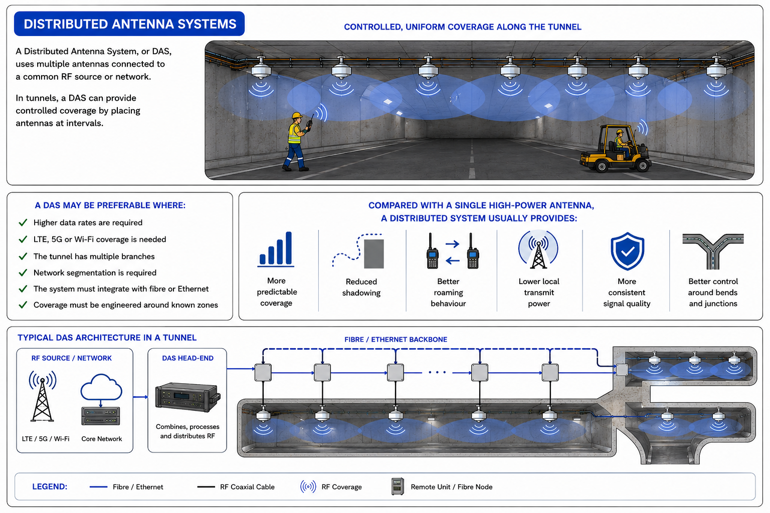
A DAS may be preferable where:
- Higher data rates are required.
- LTE, 5G or Wi-Fi coverage is needed.
- The tunnel has multiple branches.
- Network segmentation is required.
- The system must integrate with fibre or Ethernet.
- Coverage must be engineered around known zones.
Compared with a single high-power antenna, a distributed system usually provides:
- More predictable coverage.
- Reduced shadowing.
- Better roaming behaviour.
- Lower local transmit power.
- More consistent signal quality.
- Better control around bends and junctions.

¶ Antenna Placement Guidance
Correct antenna placement is often more important than antenna gain alone.
A high-gain antenna installed in the wrong position may perform worse than a lower-gain antenna installed correctly.
¶ General Placement Rules
| Design Rule | Reason |
|---|---|
| Keep antennas clear of large metal objects | Reduces detuning, shadowing and unwanted reflections. |
| Avoid mounting directly against wet rock or reinforced concrete | Reduces absorption and pattern distortion. |
| Maintain line of sight where possible | Improves the direct path and reduces reliance on reflections. |
| Use overlap between coverage zones | Prevents dead spots during roaming or movement. |
| Test several heights | Tunnel modes and reflections can vary strongly with antenna height. |
| Use circular polarization in highly reflective sections | Improves resilience against polarization changes and first reflections. |
| Add nodes before bends | Prevents corner loss from becoming a coverage failure. |
| Survey with equipment in realistic positions | Vehicles and machinery can significantly change the RF environment. |
¶ Frequency Considerations
The best frequency for underground propagation depends on the tunnel geometry, required bandwidth, antenna size and system type.
Lower frequencies generally provide:
- Better diffraction.
- Better penetration around obstructions.
- Lower free-space path loss.
- Larger antenna size.
- Lower available bandwidth.
Higher frequencies generally provide:
- Smaller antennas.
- Higher available bandwidth.
- Greater sensitivity to obstruction.
- Stronger dependence on tunnel waveguide behaviour.
- Potentially shorter range in irregular or lossy sections.
Typical underground systems may use:
| Frequency Range | Typical Use |
|---|---|
| VHF / UHF | Two-way radio, leaky feeder systems, safety communications. |
| 700 MHz – 900 MHz | Private LTE, industrial telemetry, underground IoT. |
| 1.8 GHz – 2.6 GHz | LTE / 5G, Wi-Fi backhaul, tunnel broadband. |
| 2.4 GHz / 5 GHz | Wi-Fi, sensors, short-range links. |
| Sub-GHz ISM | Low-power sensors and monitoring systems. |
Important Note
There is no single best frequency for all tunnels. A narrow dry service tunnel, a wet cave, a reinforced concrete road tunnel and a coal mine gallery may all require different RF designs.

¶ Design Strategies for Longer Range
The following methods can improve underground communication distance.
¶ 1. Use Circular Polarization Where Reflections Are Severe
Circular polarization can reduce orientation sensitivity and improve stability in reflective tunnel environments.
It is particularly useful where:
- The tunnel is narrow.
- The walls are reflective.
- Equipment moves.
- Device orientation changes.
- Linear polarization fades unpredictably.
- First reflections cause strong interference.
¶ 2. Use Directional Coverage Along the Tunnel Axis
Where communication is mainly required along one direction, use an antenna pattern that projects energy down the tunnel rather than wasting power into walls or side areas.
Directional antennas can be useful where:
- Coverage is needed along a straight tunnel.
- The transmitter is located at a portal or entrance.
- A repeater is feeding the next section.
- RF energy needs to be aimed into a branch or passage.
¶ 3. Use Repeaters Before the Signal Becomes Weak
Repeater spacing should be based on measured signal quality.
Install repeaters while there is still enough link margin for reliable operation.
Poor repeater placement can create unstable coverage if the repeater is installed at a point where the donor signal is already weak.
¶ 4. Use Leaky Feeder for Continuous Linear Coverage
For long tunnels and mines, leaky feeder systems can provide continuous distributed coverage where natural propagation is inadequate.
They are especially useful where personnel move continuously along a route and radio coverage must remain available throughout the tunnel.
¶ 5. Use DAS for High-Capacity Systems
For LTE, 5G, Wi-Fi or private network deployments, a distributed antenna system can provide more consistent signal quality than a single antenna.
A DAS can also be easier to engineer where coverage needs to be split between several areas or branches.
¶ 6. Treat Corners as Separate Coverage Zones
A 90° bend should normally be treated as a new RF section.
Do not assume coverage will naturally continue around the corner.
Coverage should be measured before and after the bend, and an additional antenna or repeater should be installed where required.
¶ 7. Survey in Real Operating Conditions
Measurements should be taken with:
- Vehicles present.
- Doors in normal positions.
- Machinery installed.
- Personnel routes considered.
- Wet or damp areas included.
- Final antenna mounting positions tested.
¶ Example Underground Coverage Designs
¶ Short Straight Tunnel
Application:
Small service tunnel, short access tunnel, straight mine gallery.
Recommended approach:
One directional or circularly polarized antenna at one end.
Suitable where:
- The route is straight.
- There are few obstructions.
- Data rate requirements are modest.
- Coverage distance is limited.
¶ Long Straight Tunnel
Application:
Long road tunnel, rail tunnel, mine haulage route.
Recommended approach:
Repeater or DAS nodes at measured intervals.
Suitable where:
- The tunnel is too long for one RF cell.
- Continuous coverage is required.
- Roaming or handover can be managed.
- Signal quality must remain consistent.
¶ Tunnel with 90° Bend
Application:
Mine branch, cave passage, service corridor.
Recommended approach:
Antenna or repeater before and after the bend.
Suitable where:
- Line of sight is lost at the bend.
- Reflections alone are unreliable.
- The branch must maintain robust coverage.
¶ Mine with Multiple Galleries
Application:
Underground mine with side passages.
Recommended approach:
Leaky feeder backbone or DAS with branch nodes.
Suitable where:
- Personnel move through multiple branches.
- Voice or safety communication is required.
- Coverage must follow the physical mine layout.
- A single antenna cannot provide reliable coverage throughout the site.
¶ Common Design Mistakes
| Mistake | Consequence |
|---|---|
| Using only free-space path-loss calculations | Real tunnel performance may be very different. |
| Assuming high gain solves all problems | High gain cannot fix poor placement, obstruction or corner loss. |
| Mounting antennas too close to metalwork | Pattern distortion and detuning may occur. |
| Ignoring polarization | Link quality may vary dramatically along the tunnel. |
| Placing repeaters too far apart | Marginal donor signal causes unstable downstream coverage. |
| Ignoring bends and junctions | Coverage may fail immediately around corners. |
| Testing before machinery is installed | Final equipment layout may create new shadow zones. |
| Measuring only received signal strength | SINR, packet loss, throughput and uplink performance may still be poor. |
¶ Best Practice Summary
For reliable RF communication in tunnels, mines and underground caves:
- Treat the tunnel as a reflective, waveguide-like channel.
- Do not assume open-air RF behaviour applies.
- Use circular polarization where reflections and orientation changes are significant.
- Use directional antennas where coverage is required along the tunnel axis.
- Use repeaters before the signal becomes marginal.
- Use leaky feeder systems for long continuous linear coverage.
- Use DAS where higher capacity or engineered LTE / 5G / Wi-Fi coverage is required.
- Treat bends, corners and branches as separate RF design zones.
- Validate performance using real measurements in final installation conditions.
- Design for signal quality, not just signal strength.
Expected Result
The reader should understand that tunnels, mines and underground caves are highly reflective RF environments. Linear antennas can suffer from unpredictable polarization changes and severe fading, while circularly polarized antennas can provide more stable performance by reducing orientation sensitivity and suppressing many first-reflection multipath components. For long underground routes, repeaters, leaky feeders and distributed antenna systems should be used to extend coverage reliably.
¶ Conclusion
Tunnels, mines and underground caves are among the most challenging environments for wireless communication.
The long, narrow geometry can help guide RF energy, but it also creates reflections, standing waves, polarization changes, obstruction loss and severe fading.
Linear polarization can work in controlled sections, but it is often unreliable across long or irregular underground routes because the dominant received polarization can change along the tunnel.
Circular polarization provides a more robust solution in many reflective underground environments because it is less sensitive to antenna rotation and can reject many first-reflection multipath components.
However, circular polarization is not a complete system design by itself.
Reliable underground communication normally requires a combination of:
- Correct antenna selection.
- Careful antenna placement.
- Measured repeater spacing.
- Coverage overlap.
- Leaky feeder or distributed antenna infrastructure.
- Real-world RF surveying.
The best underground RF systems are therefore not designed around maximum antenna gain alone.
They are designed around controlled coverage, polarization resilience, link margin, redundancy and measured performance in the actual tunnel environment.
¶ About Siretta
Siretta provides RF connectivity solutions for challenging industrial environments, including mining, tunnelling and underground infrastructure. From signal surveys and antenna selection to RF cables and supporting accessories, we can help you choose the right components for reliable underground wireless communications.
If you're planning a new installation or upgrading an existing system, contact Siretta to discuss your application and technical requirements with our engineering team.
