|
|
¶ General Description
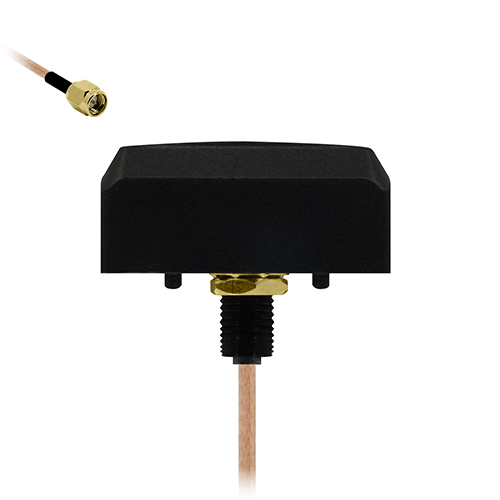
The Tango 21 combines a compact footprint with a robust screw-mount design, making it Siretta’s smallest screw-mount GPS antenna. Operating on the GPS L1 frequency, it supports GPS, Galileo E1, BeiDou B1C and QZSS L1 satellite systems, while its space-saving construction allows discreet and secure integration into embedded equipment, tracking devices and applications where installation space is limited.
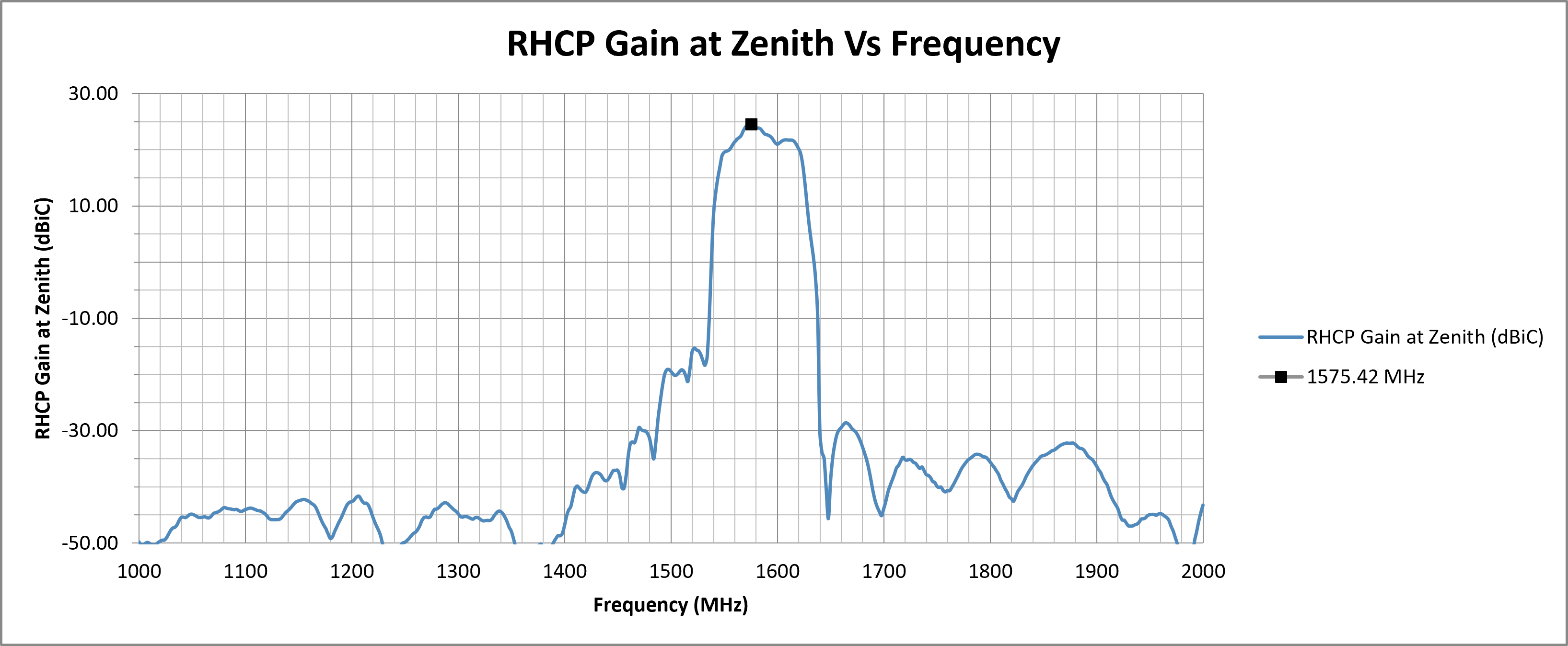
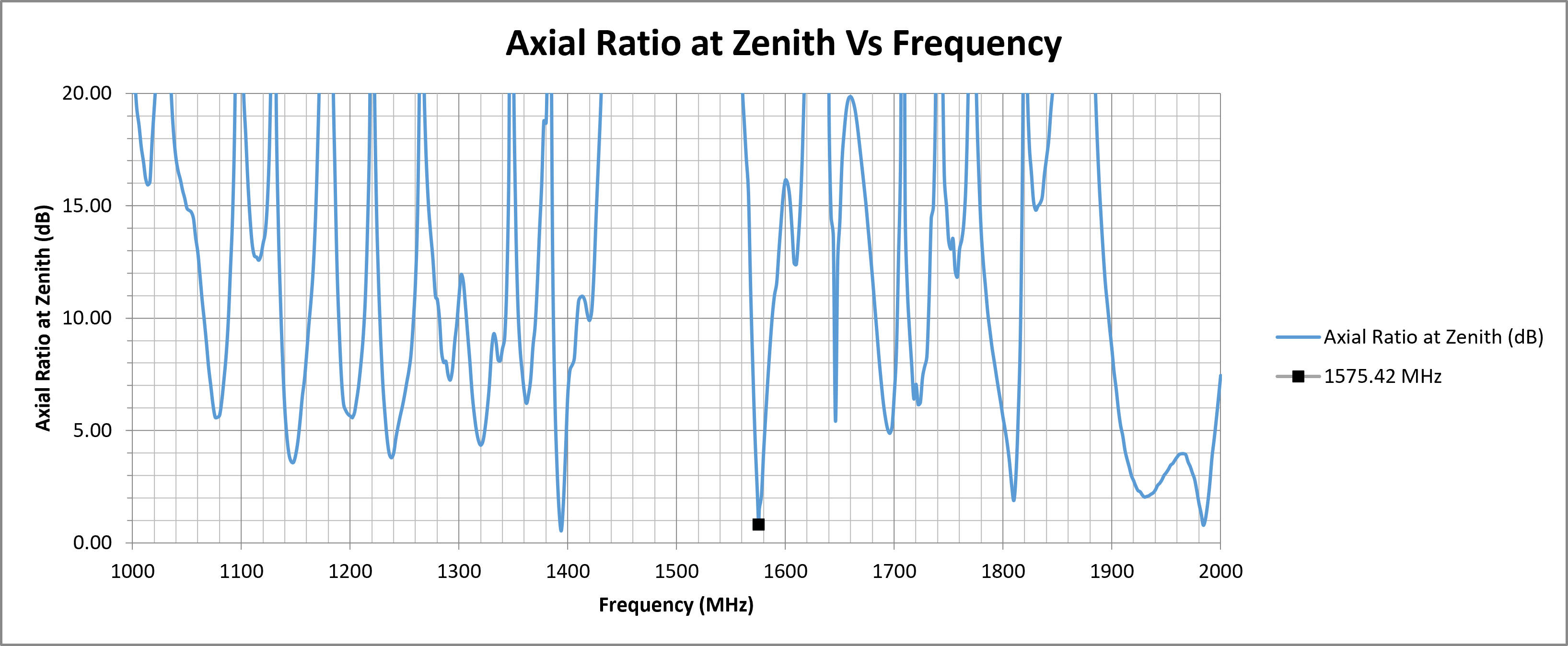
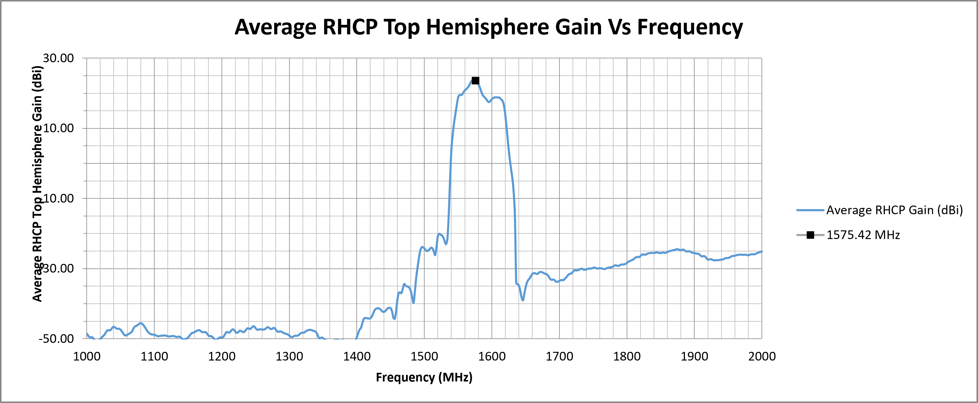
Equipped with a built-in Low Noise Amplifier (LNA), the Tango 21 delivers up to 22 dBiC gain to enhance satellite signal reception, helping to reduce acquisition times and support faster positioning. With top-hemisphere RHCP gain of 22 dBiC and an axial ratio of 3 dB at zenith, it maintains good circular polarisation performance for reliable GNSS reception in environments affected by multipath interference.
The Tango 21 is supplied as standard with IPEX, MCXM Male or SMA Male connectors and cable lengths of 210 mm, 300 mm or 3 m, depending on the connector configuration. Alternative cable lengths and connector types are available for high-volume orders.
¶ Key Features
- Supports GPS L1 frequency at 1575.42 MHz
- High RHCP gain of 22 dBiC
- 3 dB axial ratio at zenith
- Robust M10 screw-mount design for secure mounting
- Durable, weather-resistant ABS enclosure suitable for exposed or vandal-prone locations
¶ Typical Applications
- Vehicle tracking and fleet management
- Embedded GNSS modules in industrial devices
- Compact and covert asset tracking
- Smart metering and remote monitoring systems
- Outdoor positioning in challenging environments
|
GPS
L1 Antenna
|
UV & Water Resistant
Outdoor Radome
|
Active Antenna
Integrated LNA
|
Through-Hole
Concealed Cable Mount
|
Low-Profile Design
Compact Installation
|
¶ Electrical Specifications
| Impedance: | 50 Ohm |
| Polarisation: | RHCP |
| Frequency Range: | 1575.42 MHz |
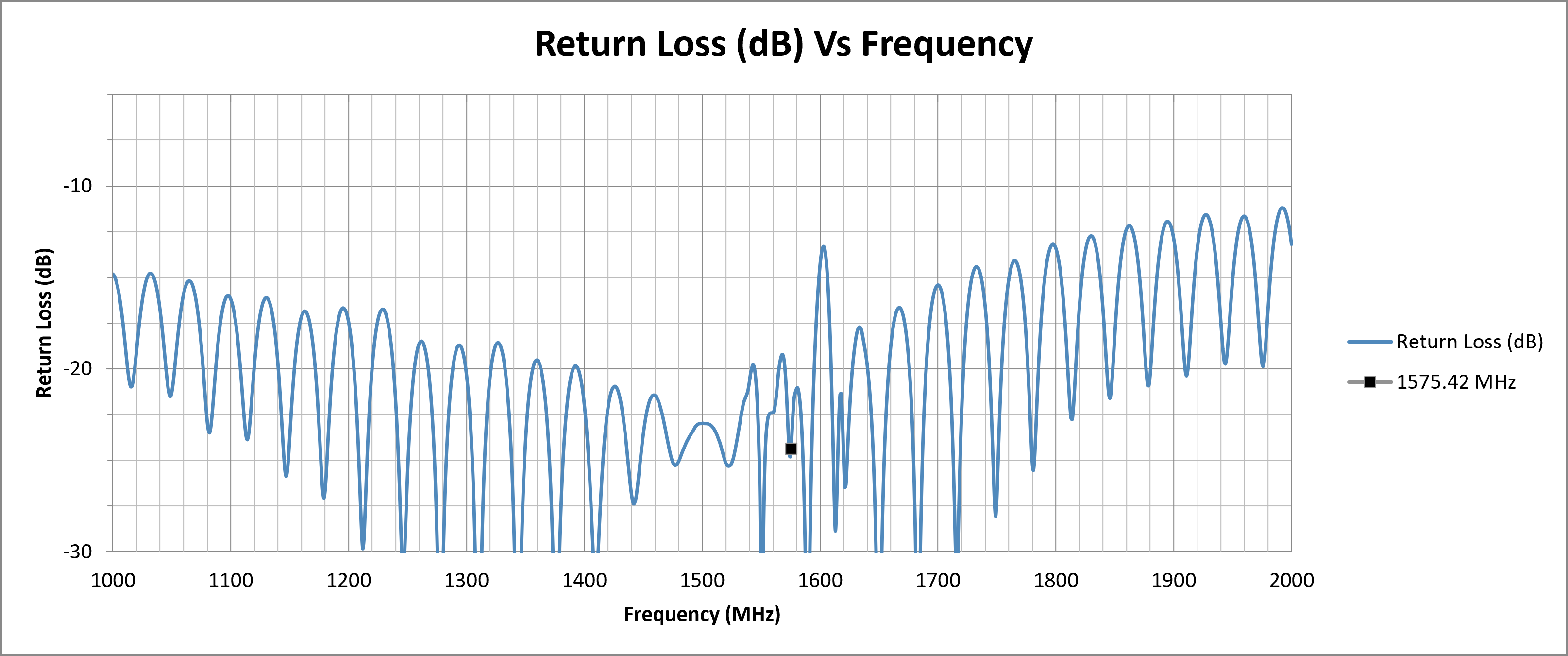
| Return Loss: | −24.4 dB |
| VSWR: | 1.13 |
| Required Ground Plane: | 200 mm circular |
| Filter Insertion Loss: | <3 dB |
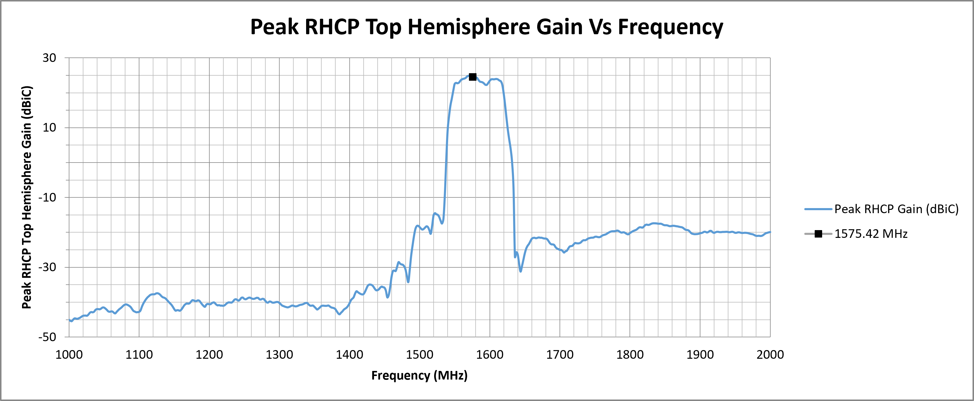
| Peak RHCP Gain (Top Hemisphere): |
24.55 dBiC |
| Axial Ratio at Zenith: | 0.88 dB |
| Noise Figure: | <1.5 dB |
| Supply Voltage: | 2.2–5 V DC |
| Current Consumption: | 5–15 mA |
¶ Environmental Specifications
| Operating Temperature range: | -40°C to 85 °C |
| Storage Temperature range: | -40°C to 85 °C |
| Relative Humidity: | Up to 95% |
¶ Mechanical Specifications
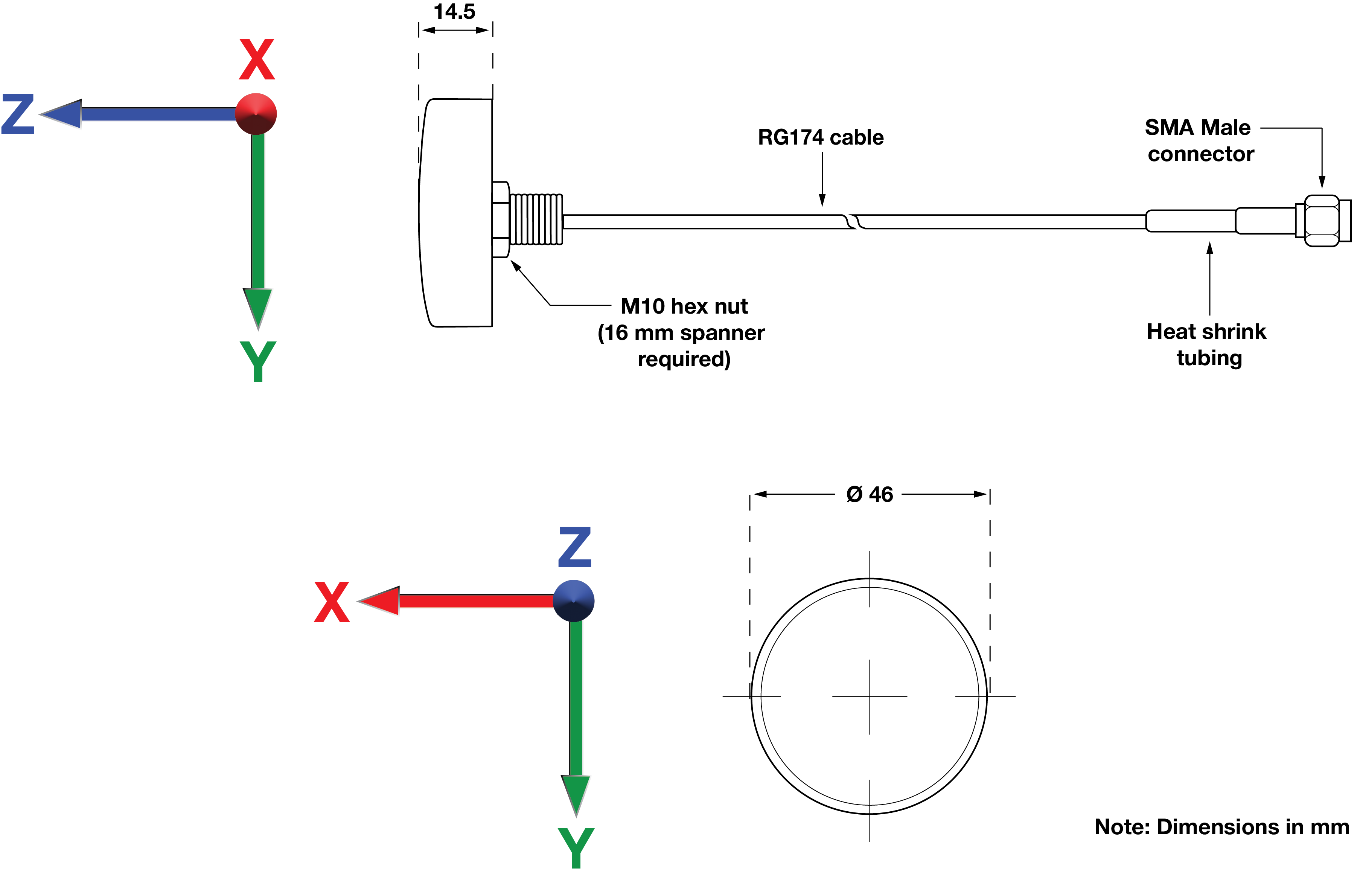
| Dimensions: | Ø 46 mm × H 14.5 mm |
| Weight: | 74 g |
| Cable Type: | RG174 |
| Cable Length: | 3 m (standard) |
| Connector: | SMA Male |
| Mounting Method: | M10 screw thread |
| Maximum Material Thickness: | 4.5 mm |
| Housing Material: | ABS |
¶ Spectrum Coverage*
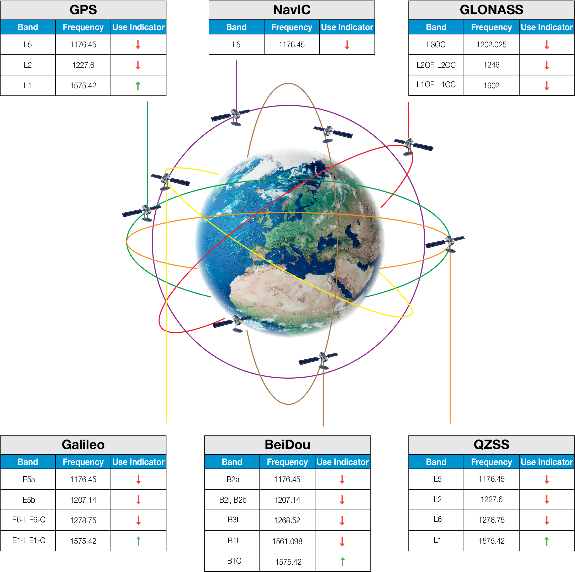
| ↑ Suitable band | □ Adequate band in good signal conditions | ↓ Likely to be unsuitable |
¶ GNSS Standards Band Support
| Electrical Interface | Spherical RF Measurements | |||||
|---|---|---|---|---|---|---|
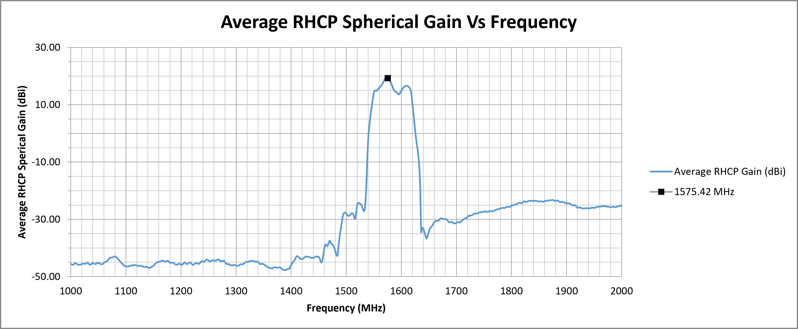
| Centre Frequency (MHz) | VSWR | Return Loss (dB) | Average RHCP Gain (dBiC) | Peak RHCP Gain (dBiC) | Median Axial Ratio (dB) | Minimum Axial Ratio (dB) |
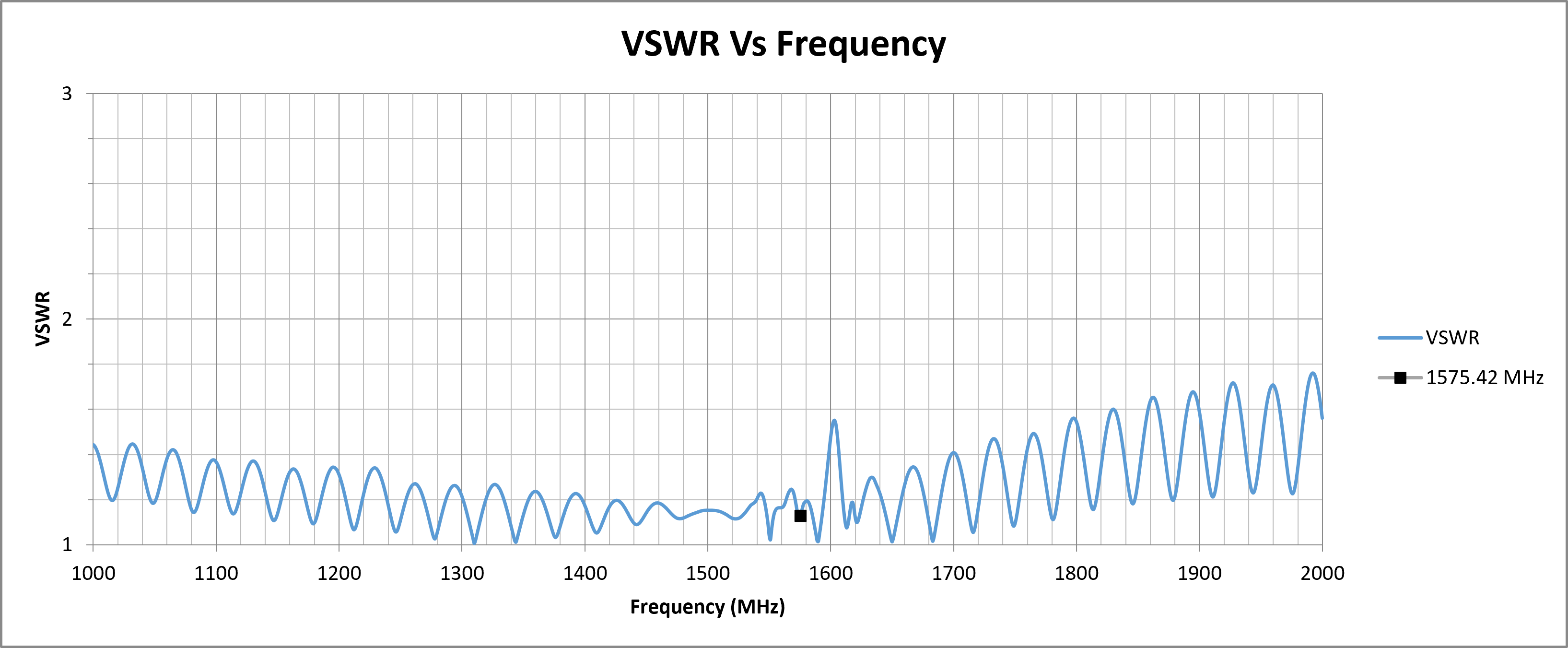
| 1575.42 (L1) | 1.1292 | -24.3579 | 19.42 | 24.55 | 5.92 | 0.18 |
| Top Hemisphere RF Measurements | Zenith RF Measurements | |||||
|---|---|---|---|---|---|---|
| Centre Frequency (MHz) | Average RHCP Gain (dBiC) | Peak RHCP Gain (dBiC) | Median Axial Ratio (dB) | Minimum Axial Ratio (dB) | RHCP Gain at Zenith (dBiC) | Axial Ratio at Zenith (dB) |
| 1575.42 (L1) | 23.67 | 24.55 | 2.31 | 0.18 | 24.53 | 0.82 |
¶ RF Matching Performance
This section illustrates the antenna's impedance matching characteristics across the operating frequency range using VSWR and Return Loss measurements.
¶ RF Zenith
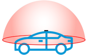
¶ RF Top Hemisphere
¶ RF Spherical
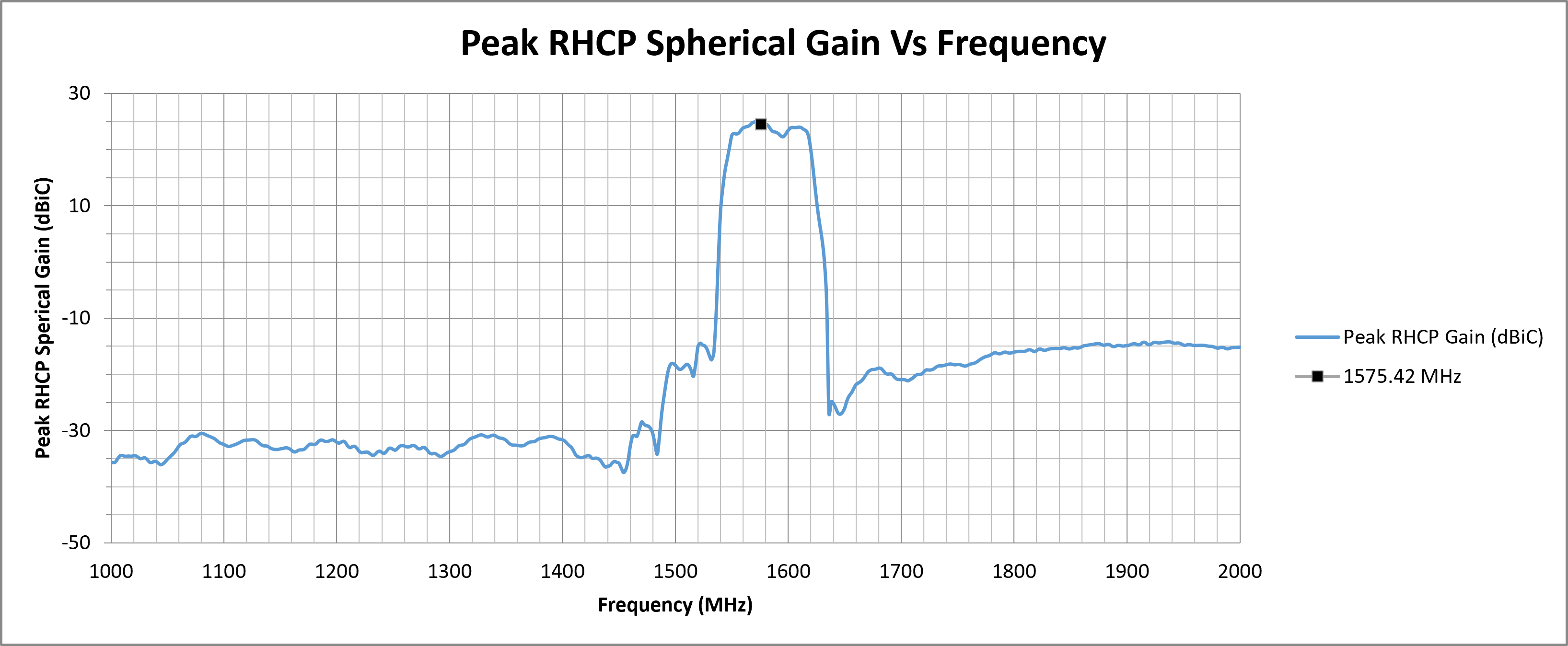
The following graphs display the Average and Peak RHCP Gain across the entire spherical coverage of the antenna. These metrics provide a comprehensive view of the antenna’s ability to receive signals from satellites at all elevations and directions.
Consistently high gain across the sphere ensures strong and stable GNSS reception in a variety of operating conditions.

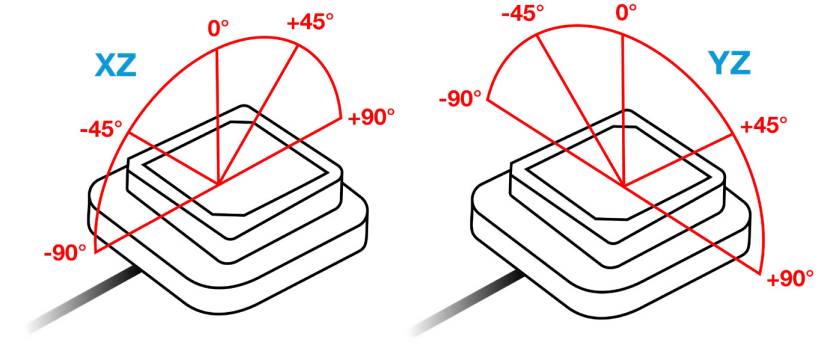
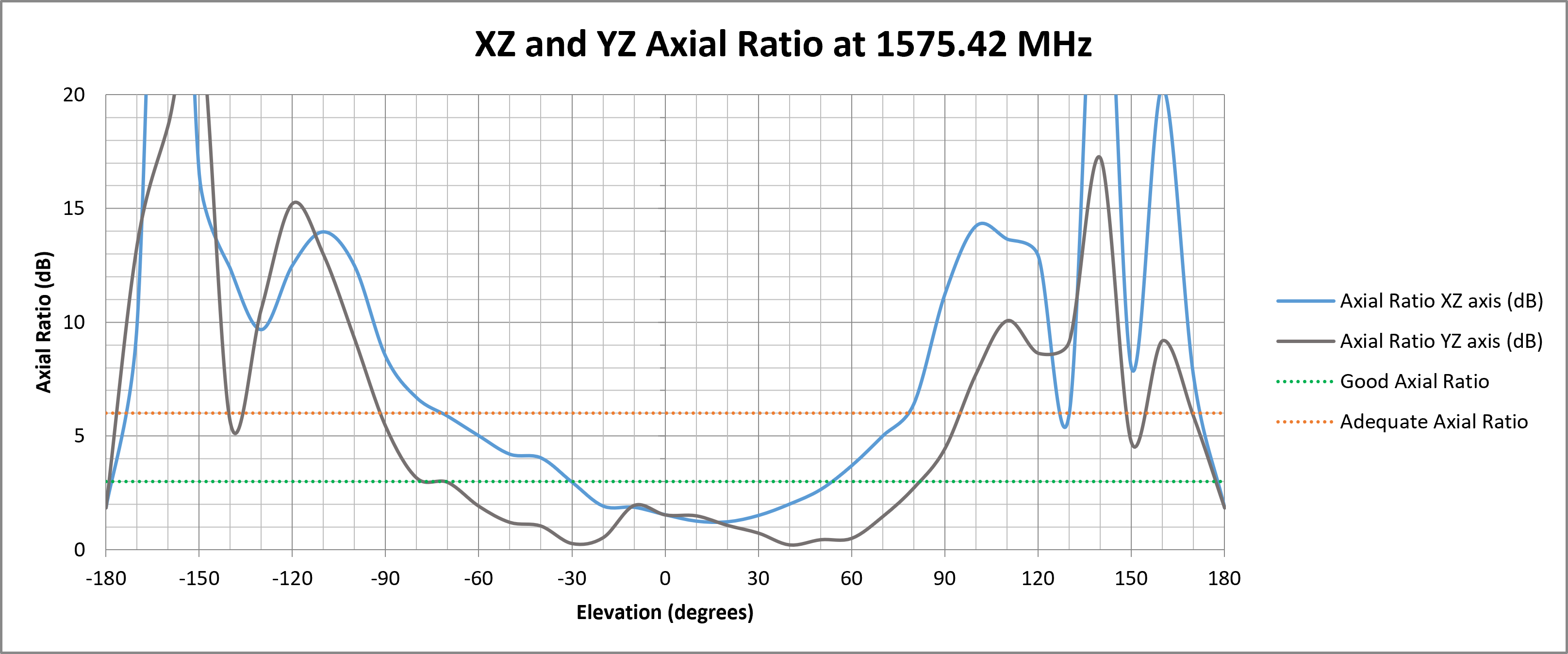
¶ ZX and YZ Plane Axial Ratio Plots (Zenith is at 0 degrees)
The following graph shows how well the antenna maintains circular polarisation at different elevation angles. A lower axial ratio ensures better GNSS signal reception, especially at low elevations, which is crucial for applications requiring strong performance in obstructed environments or wide-angle satellite visibility.
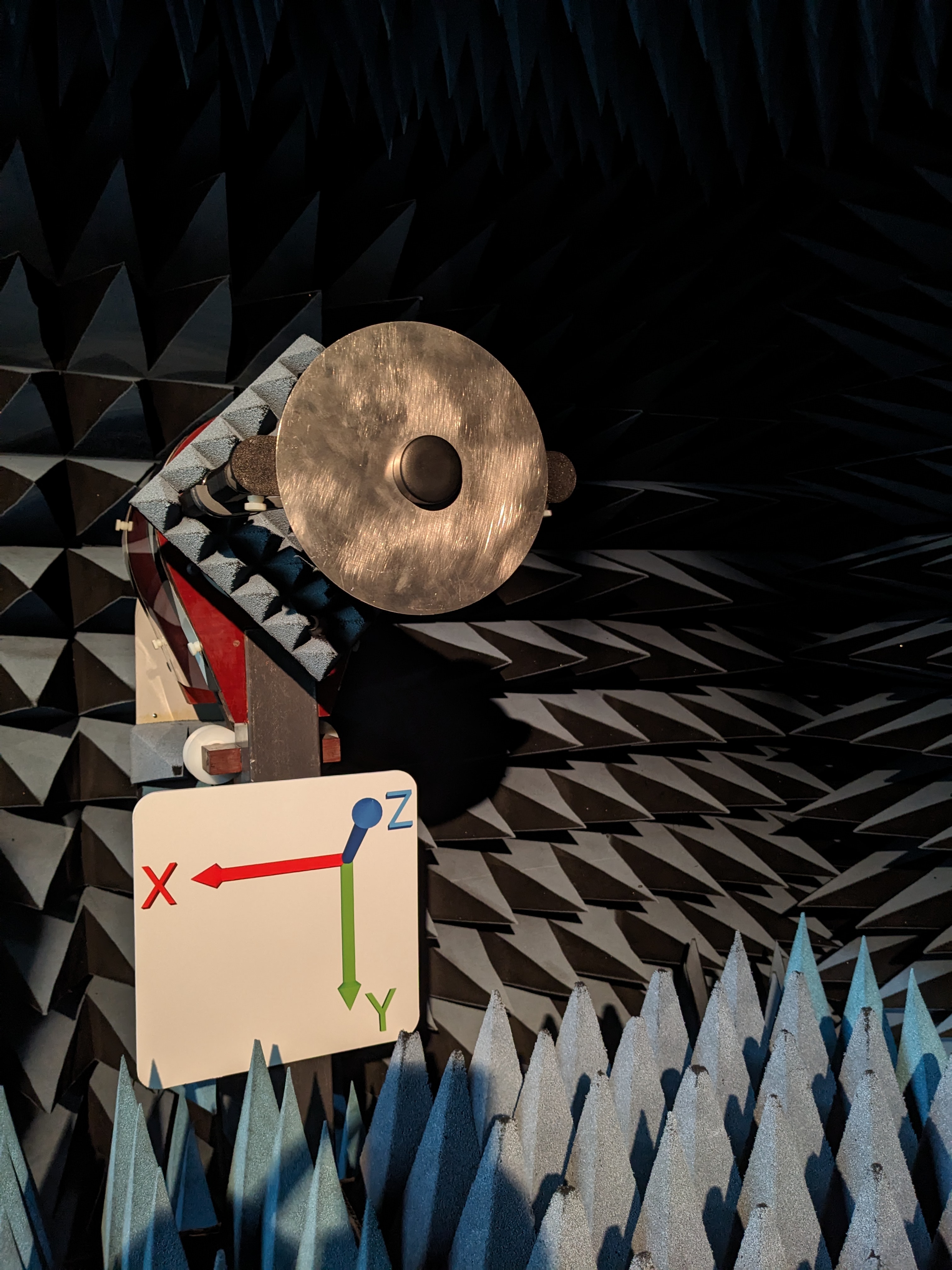
¶ Test Setup (on 200 mm Circular Ground Plane)
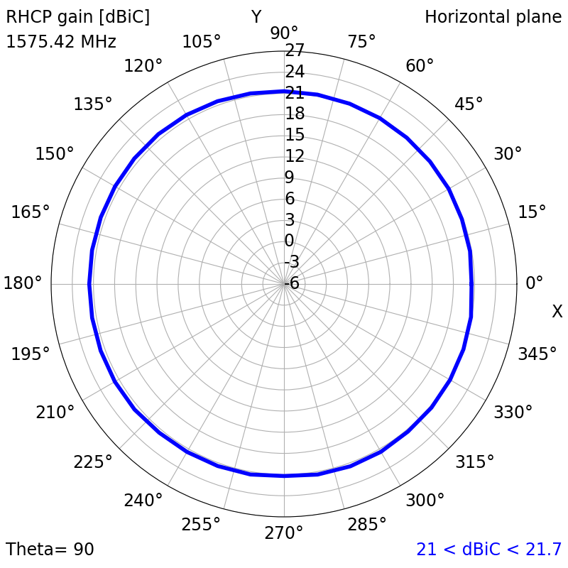
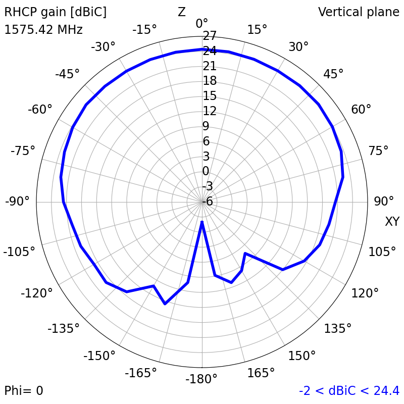
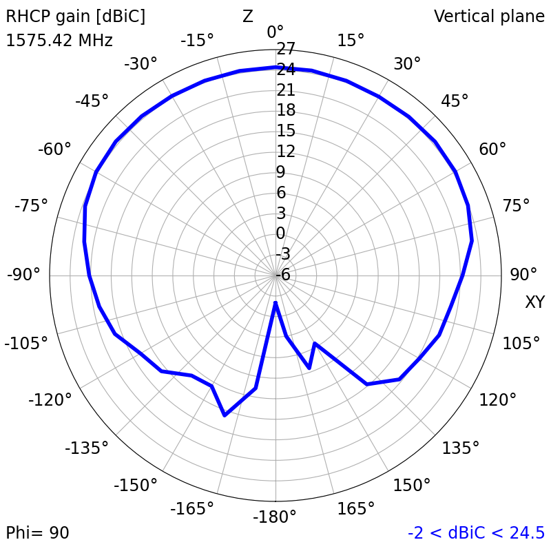
¶ 2D Radiation Plots
1575.42 MHz (L1)
|
|
|
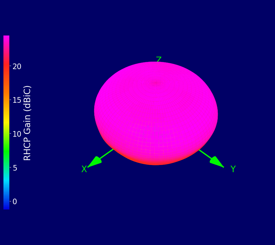
¶ 3D Radiation Plots
1575.42 MHz (L1)
¶ Ordering Details
| Part Number | Description |
|---|---|
| TANGO20/3M/SMAM/S/S/26 |
Active GPS L1 Screw-Mount Puck Antenna 3 m RG174 Cable and SMA Male Connector |