|
|
¶ General Description
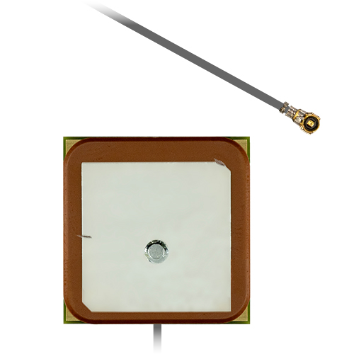
The Echo 67 is an active embedded GPS antenna developed for equipment requiring stable reception of the 1575.42 MHz L1 band. Its PCB-mount construction, as well as its integrated LNA, ground plane and cable assembly makes integration into OEM products easy and straightforward.
An integrated low-noise amplifier (LNA) enhances weak L1 GNSS signals directly at the antenna, reducing the effects of system noise before the signal reaches the host device. Delivering a reliable 27 dB of top-hemisphere gain, the Echo 67 provides strong right-hand circular polarisation for accurate position updates and robust satellite tracking.
Weighing only 12 grams, this 25 by 25 mm patch antenna is ideal for space-constrained electronic equipment where reliable L1 GNSS reception is required.
Pre-fitted with a 100 mm miniature coaxial cable assembly for easy integration with any I-PEX MHF1 and UFL compatible module (other cable lengths and connector types are available for high volume requirements).
¶ Key Features
- Supports GPS L1, Galileo E1, BeiDou B1C, and QZSS L1
- Integrated LNA for enhanced satellite signal reception
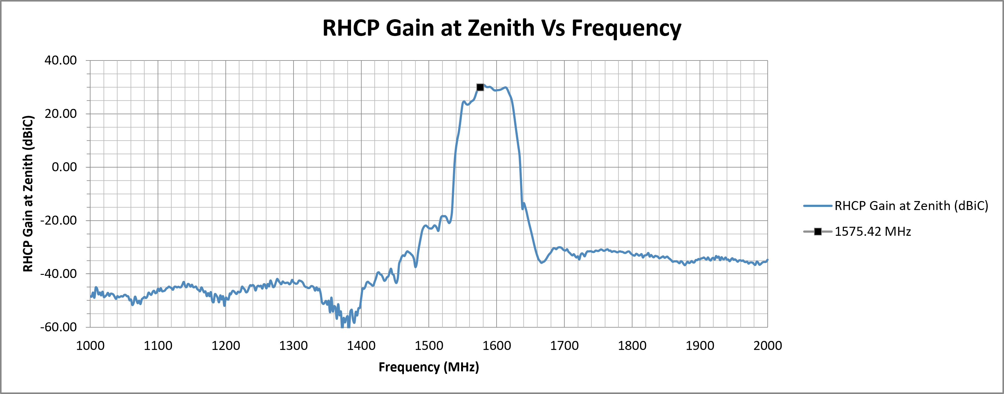
- Top hemisphere RHCP gain up to 30.38 dBiC
- Excellent impedance matching for efficient signal transfer
- Compact PCB-mount design for straightforward OEM integration
¶ Typical Applications
- Industrial automation and process control equipment
- Vehicle telematics and fleet management systems
- Surveying and mapping equipment
- Smart infrastructure and monitoring systems
- Precision agriculture and guidance equipment
|
GPS
L1 Antenna
|
Active
Integrated LNA
|
Embedded
Installation
|
¶ Electrical Specifications
| Impedance: | 50 Ohm |
| Polarisation: | RHCP |
| Frequency Range: | 1575.42 MHz |
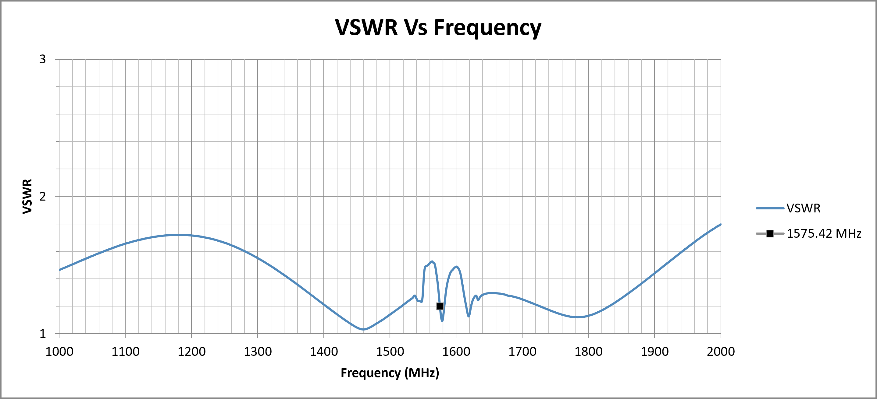
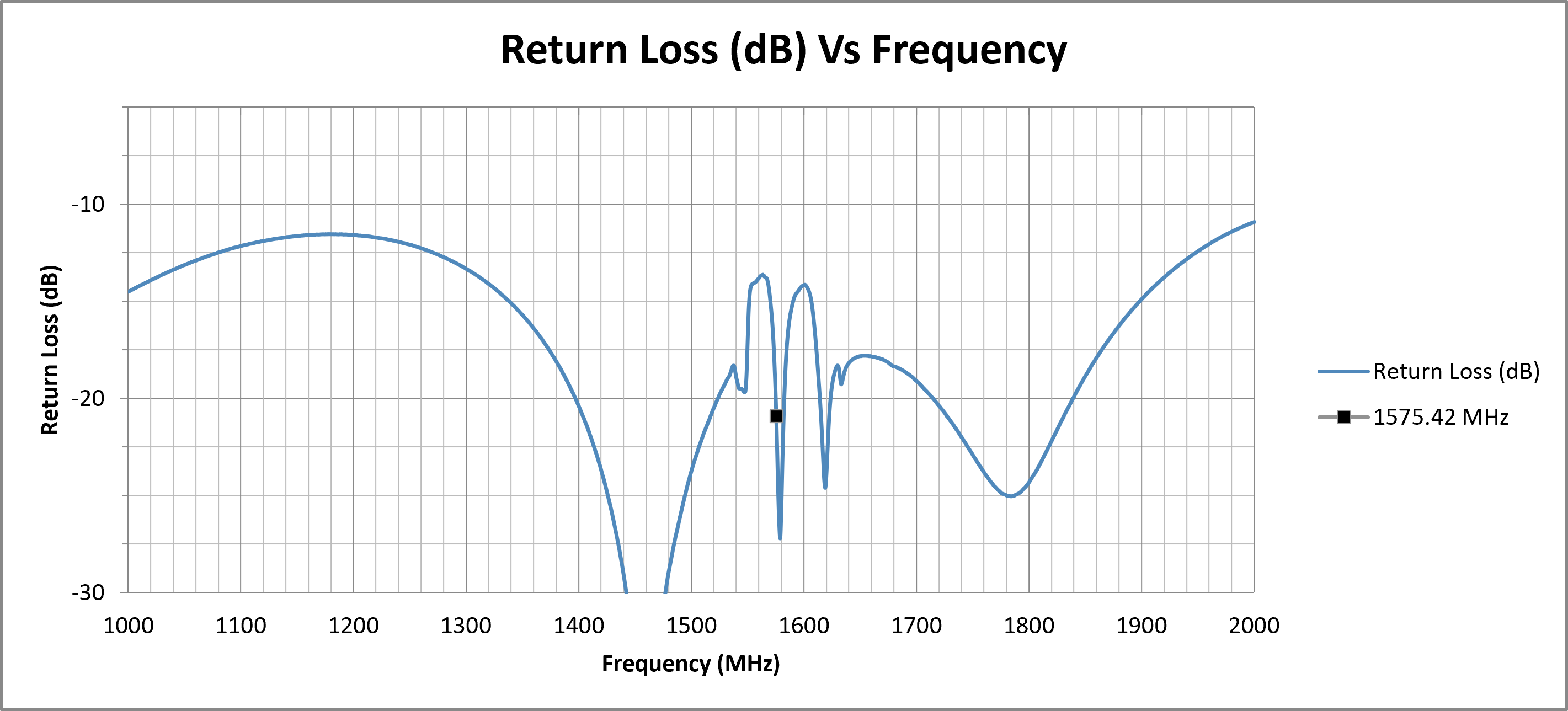
| Return Loss: | -20.90 dB |
| VSWR: | 1.20 |
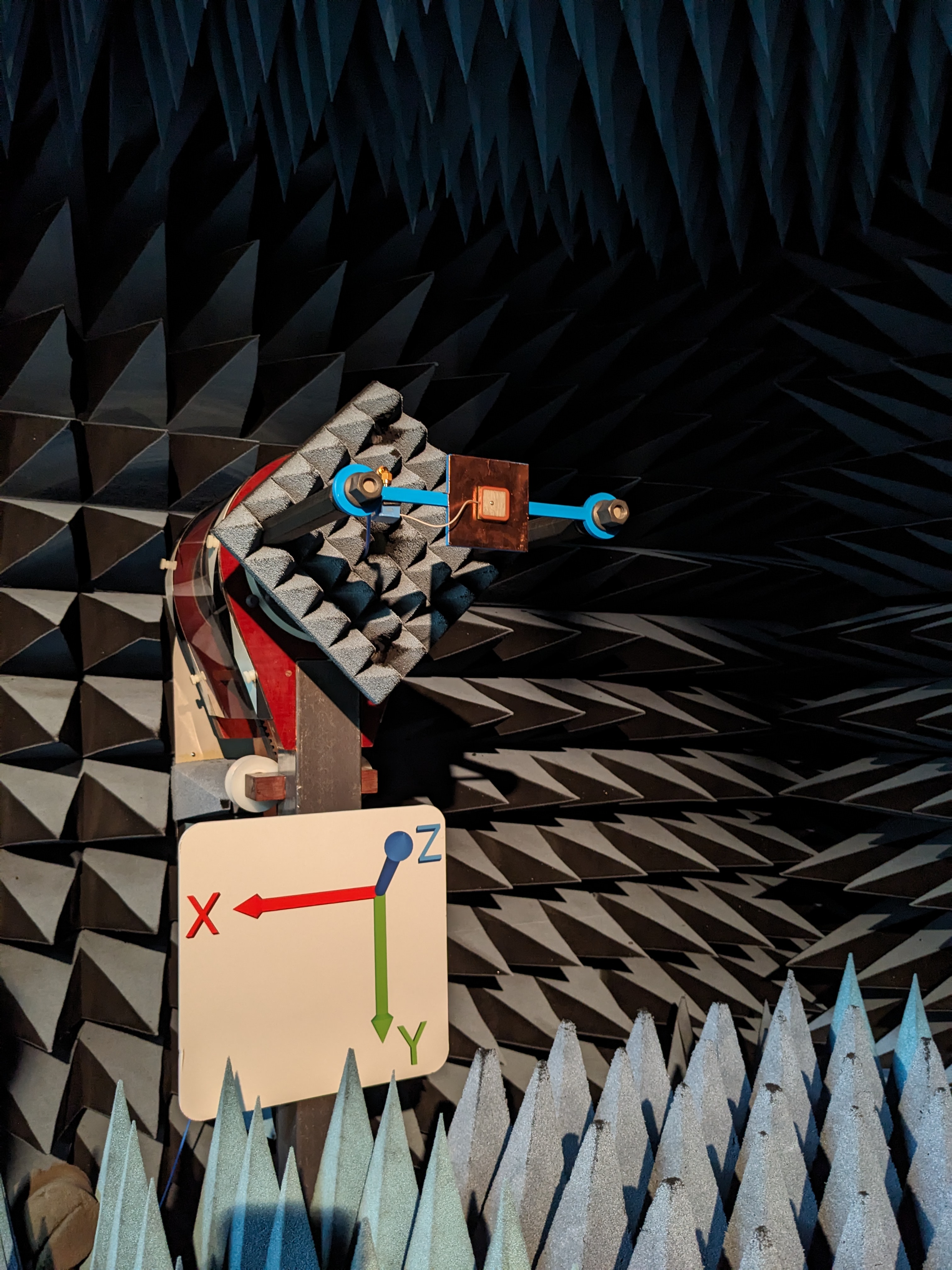
| Ground plane: | tested on 70 x 70 mm ground plane |
| RHCP Gain: | 27 ±3 dBiC |
| Axial Ratio at Zenith: | 14.88 dB |
| Supply Voltage: | 3 - 5 V DC |
| Current Consumption: | ≤ 11 mA |
¶ Environmental Specifications
| Operating Temperature range: | -40°C to 80°C |
| Storage Temperature range: | -40°C to 80°C |
¶ Mechanical Specifications
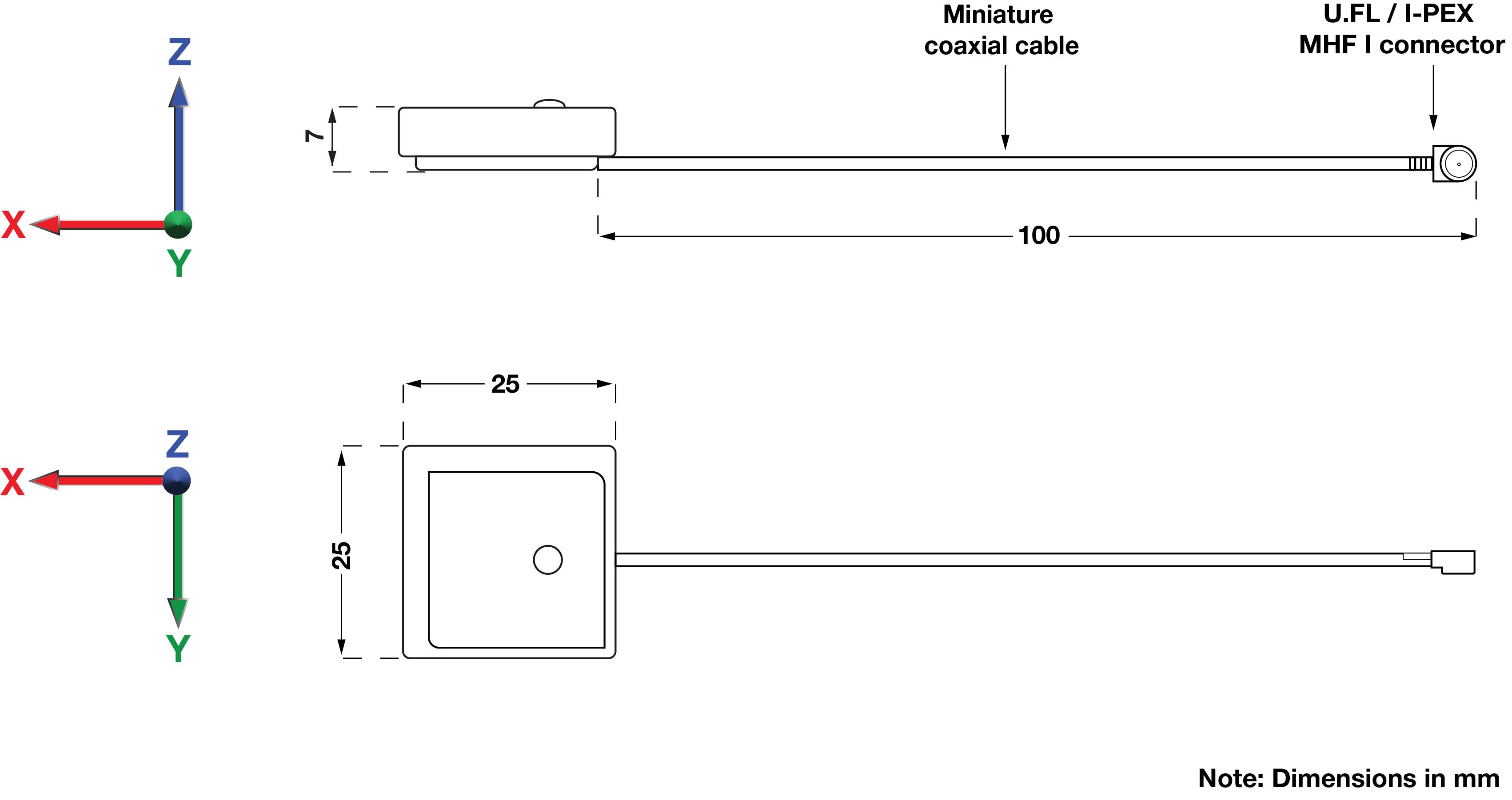
| Dimensions: | L = 25 mm W = 25 mm H = 7 mm |
| Weight: | 12 g |
| Cable Type: | Miniature Coaxial |
| Cable Length: | 100 mm |
| Connector: | U.FL / I-PEX MHF I |
| Mounting method: | Embedded |
¶ Spectrum Coverage*
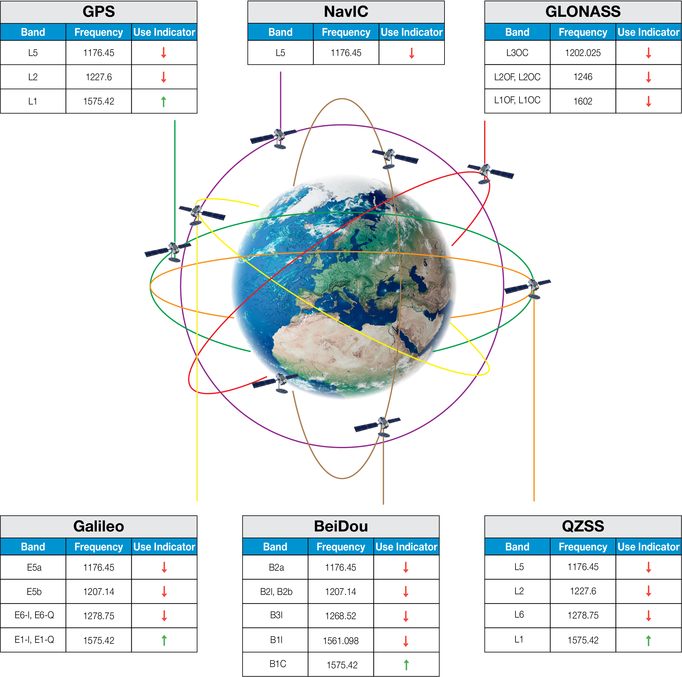
| ↑ Suitable band | □ Adequate band in good signal conditions | ↓ Likely to be unsuitable |
¶ GNSS Standards Band Support
| Electrical Interface | Spherical RF Measurements | |||||
|---|---|---|---|---|---|---|
| Centre Frequency (MHz) | VSWR | Return Loss (dB) | Average RHCP Gain (dBiC) | Peak RHCP Gain (dBiC) | Median Axial Ratio (dB) | Minimum Axial Ratio (dB) |
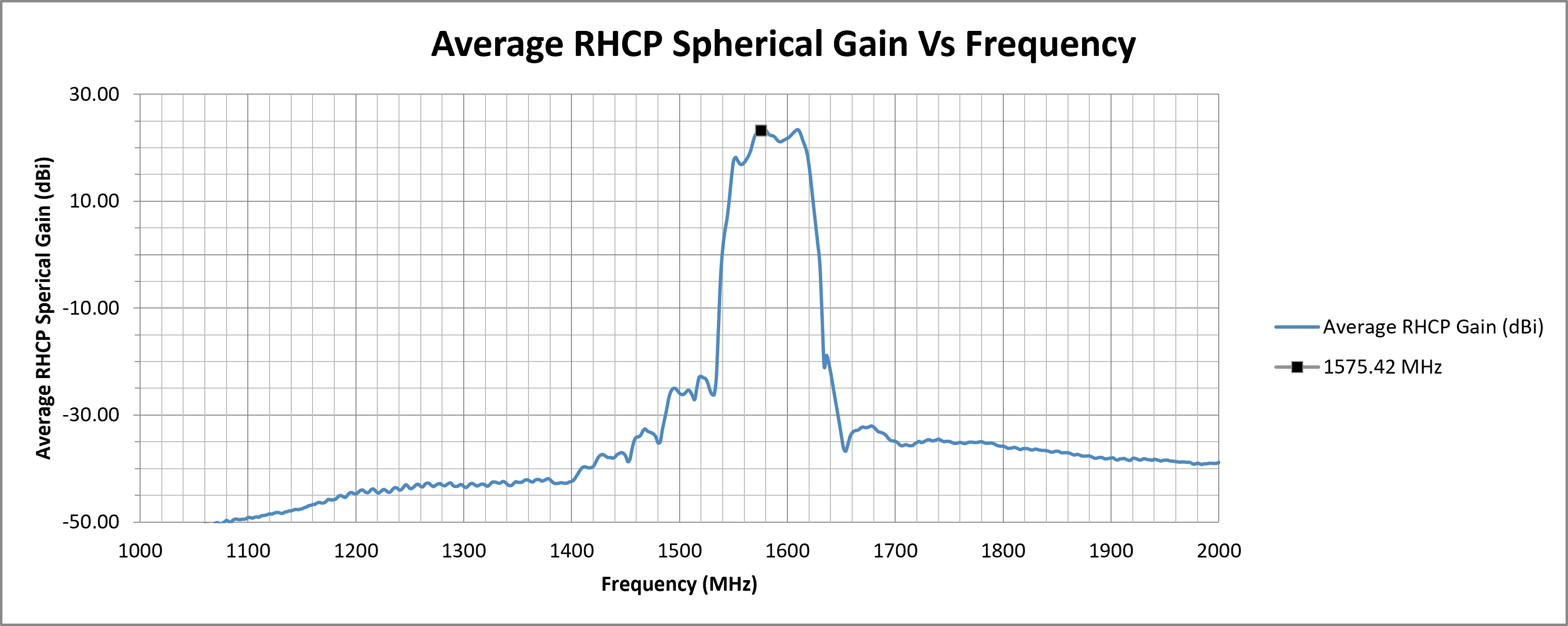
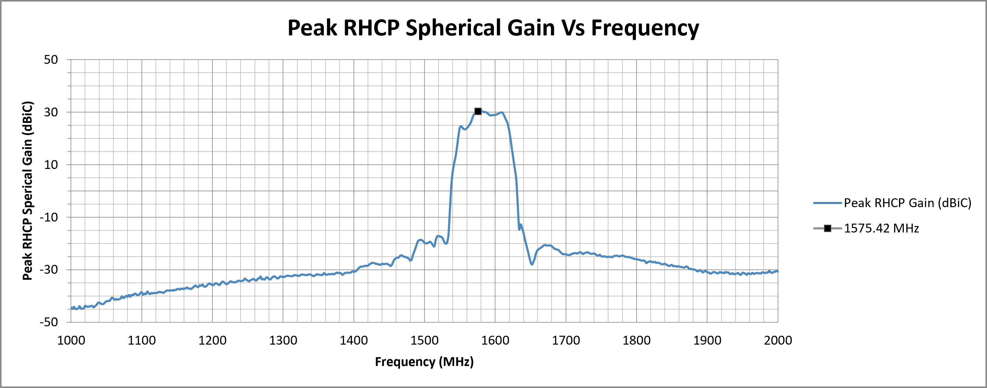
| 1575.42 | 1.2000 | -20.8982 | 23.22 | 30.38 | 13.52 | 0.26 |
| Top Hemisphere RF Measurements | Zenith RF Measurements | |||||
|---|---|---|---|---|---|---|
| Centre Frequency (MHz) | Average RHCP Gain (dBiC) | Peak RHCP Gain (dBiC) | Median Axial Ratio (dB) | Minimum Axial Ratio (dB) | RHCP Gain at Zenith (dBiC) | Axial Ratio at Zenith (dB) |
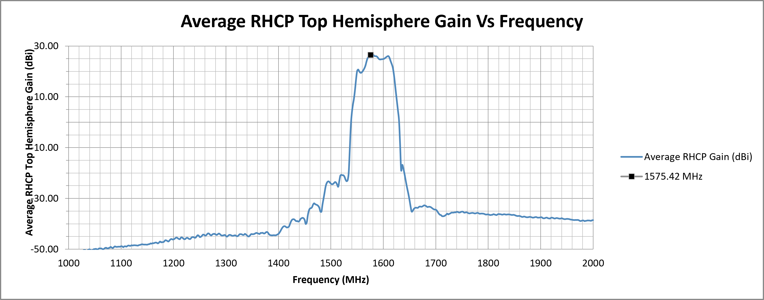
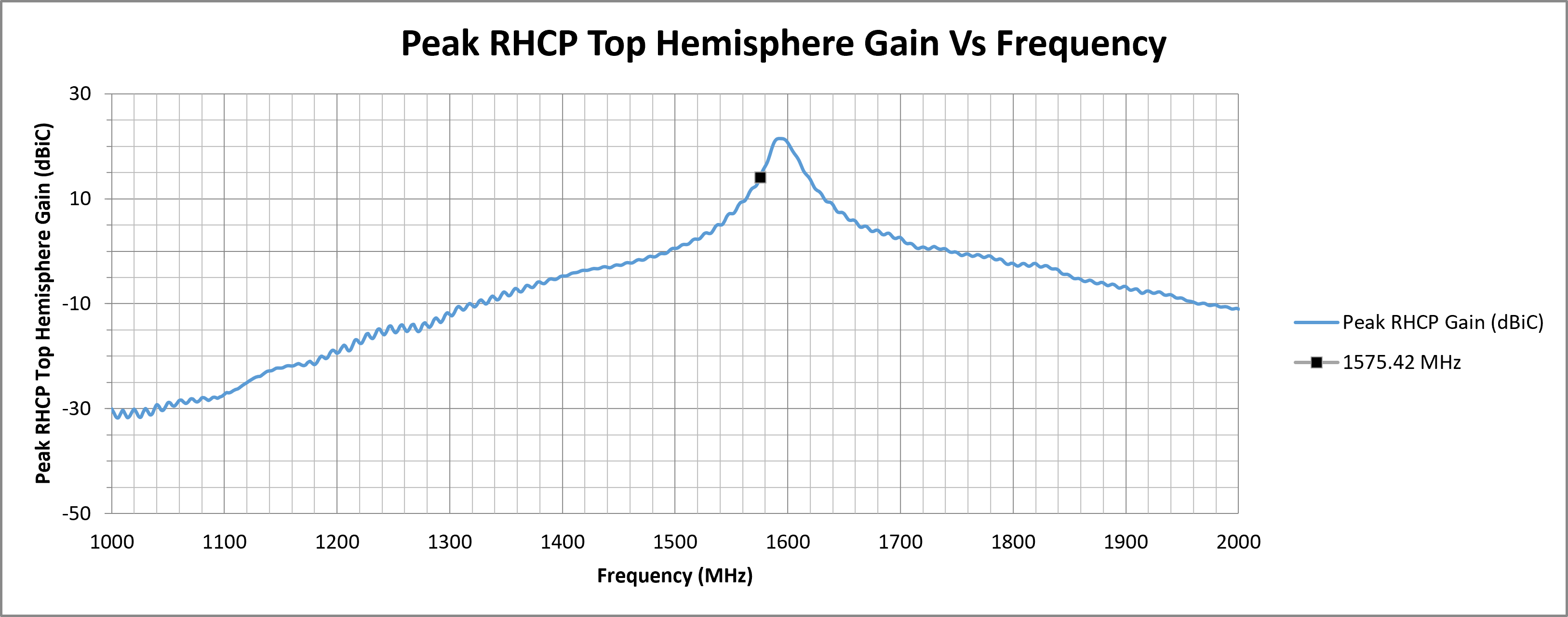
| 1575.42 | 26.49 | 30.38 | 15.18 | 2.02 | 29.97 | 14.88 |
¶ RF Matching Performance
This section illustrates the antenna's impedance matching characteristics across the operating frequency range using VSWR and Return Loss measurements.
¶ RF Zenith
¶ RF Top Hemisphere
¶ RF Spherical
The following graphs display the Average and Peak RHCP Gain across the entire spherical coverage of the antenna. These metrics provide a comprehensive view of the antenna’s ability to receive signals from satellites at all elevations and directions.
Consistently high gain across the sphere ensures strong and stable GNSS reception in a variety of operating conditions.

¶ Test Setup (on 70 x 70 mm Ground Plane)
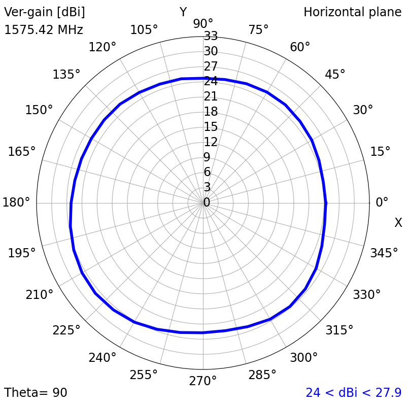
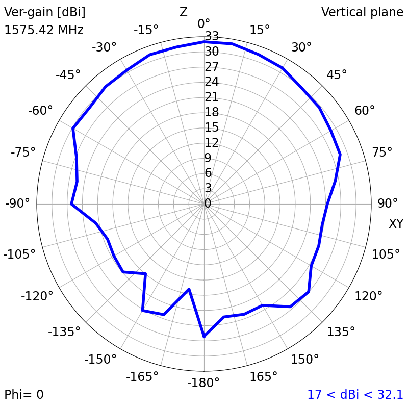
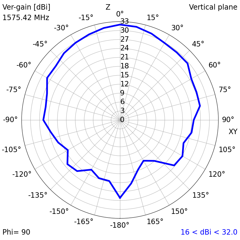
¶ 2D Radiation Plots (1575.42 MHz)
|
|
|
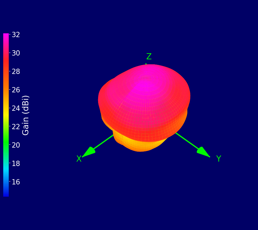
¶ 3D Radiation Plots (1575.42 MHz)
¶ Ordering Details
| Part Number | Description |
|---|---|
| ECHO67/0.1M/UFL/S/S/48 |
25 x 25 mm Active Ceramic Patch GPS L1 Embedded Antenna 0.1 Metre Miniature Coaxial Cable and U.FL / I-PEX MHF I Connector |