Reference Centre
Return to the Antenna Application Notes
Overview
RF cable assemblies play a critical role in overall antenna system performance. Poor cable selection, excessive cable length or poor connector quality can significantly reduce signal strength, increase losses and negatively impact LTE, 5G, GNSS and IoT communications.
¶ Introduction
Significant effort is often invested into selecting the correct antenna for an RF system, but the performance of the RF cable assembly between the antenna and modem is equally important.
Even the highest gain antenna can perform poorly if excessive cable loss exists between the antenna and the radio.
This application note explains:
- cable attenuation
- RF cable construction
- shielding effectiveness
- return loss
- impedance mismatch
- connector quality
- cable length effects
- installation best practices
- the impact of poor cable quality on IoT and cellular systems
¶ Why RF Cable Quality Matters
RF cable losses directly affect:
- transmitted signal power
- received signal sensitivity
- LTE and 5G throughput
- GNSS reception
- IoT battery life
- retransmissions
- modem reliability
- network stability
Cable attenuation reduces both transmitted and received signal levels.
Important Note
RF cable attenuation reduces the overall link budget of the system. Losses apply equally to transmitted and received signals.
¶ Cable Attenuation
Attenuation is the reduction in RF signal strength as energy travels through the cable.
Losses are caused by:
- conductor resistance
- dielectric losses
- shield losses
- connector transitions
- impedance mismatch
- manufacturing tolerances
- skin effect
Higher frequencies experience greater attenuation than lower frequencies.
¶ Cable Attenuation Comparison
The following graph compares attenuation characteristics of common RF cable types.
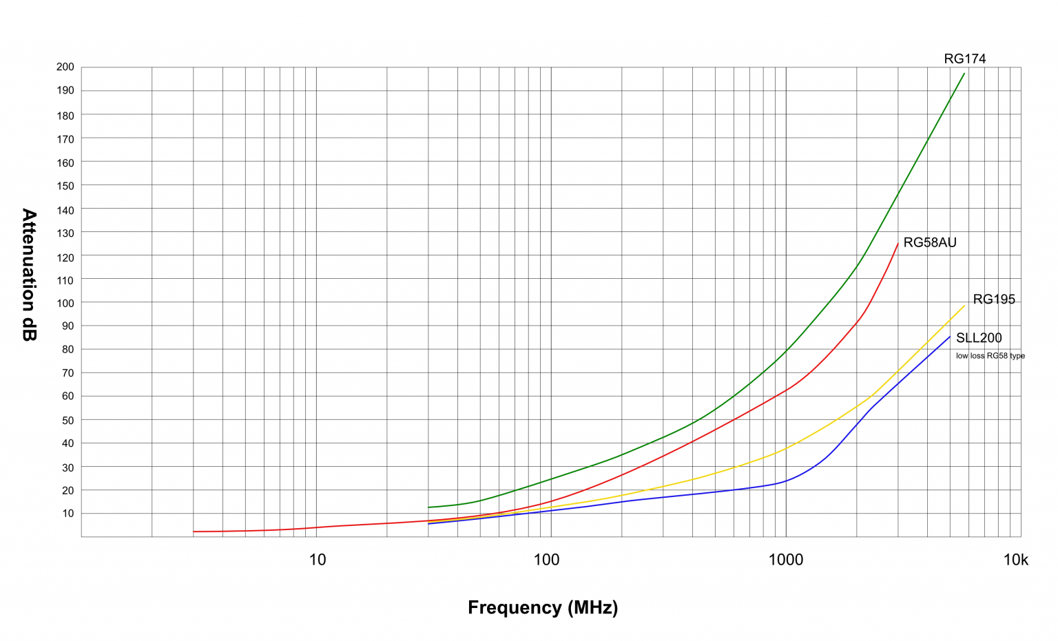
Cable attenuation is normally specified as:
- dB per metre
- dB per 100 metres
¶ Cable Length vs Signal Loss
The following graph demonstrates how cable losses increase over distance.
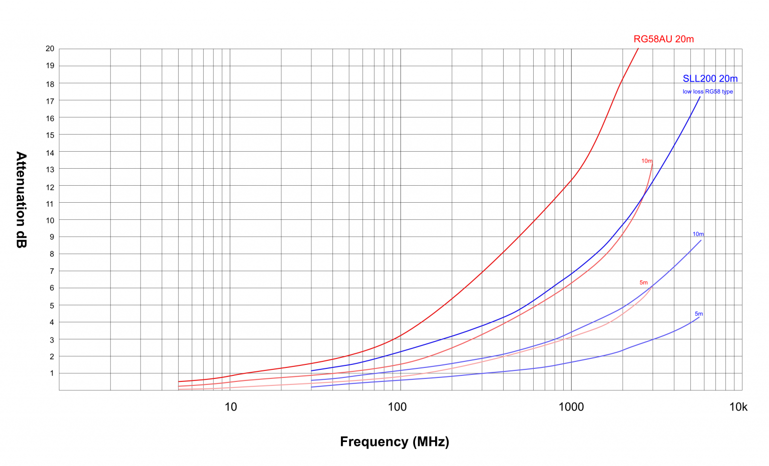
Even relatively short cable lengths can introduce significant losses at LTE, 5G and GNSS frequencies.
¶ Frequency Dependency
Cable attenuation increases with operating frequency.
Higher-frequency systems such as:
- LTE high band
- 5G NR
- WiFi
- GNSS
are therefore more sensitive to cable quality and cable length.
| Frequency Range | Typical Attenuation Behaviour |
|---|---|
| Sub-GHz | Lower attenuation |
| 1-2 GHz | Moderate attenuation |
| 2-6 GHz | Higher attenuation |
| Above 6 GHz | Very high attenuation |
¶ Typical RF Cable Construction
The following image shows the internal construction of a typical coaxial RF cable.
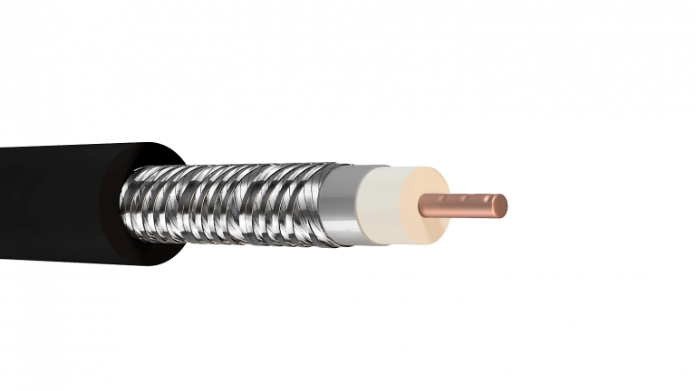
A coaxial cable typically consists of:
- centre conductor
- dielectric insulation
- shield braid
- foil shield
- external jacket
Each layer contributes to overall RF performance.
¶ Coaxial Cable Internal Structure
The physical dimensions and geometry of the cable directly affect impedance and RF performance.
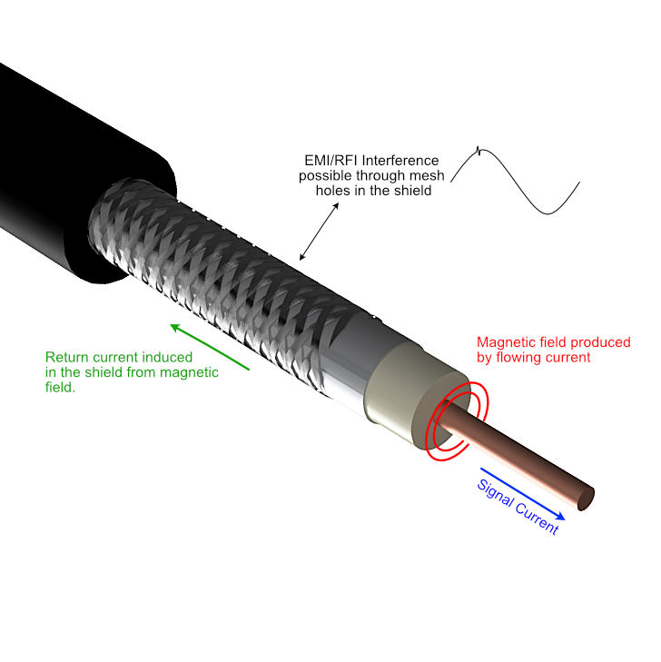
Variations in:
- conductor position
- dielectric consistency
- shield geometry
can affect:
- impedance stability
- return loss
- attenuation
¶ What is Skin Effect?
At RF frequencies, signals primarily travel on the outer surface of the conductor.
This behaviour is known as skin effect.
As frequency increases:
- the conduction depth decreases
- conductor surface quality becomes increasingly important
¶ SMA Connector Internal Structure
The following image shows a typical SMA connector internal structure.
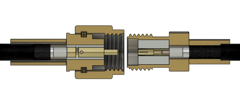
Signal transitions through:
- centre pins
- sockets
- mating surfaces
- varying conductor geometries
These transitions are never perfectly smooth.
¶ RF Signal Transition Through Connector
RF signals are sensitive to abrupt impedance changes.
The following image illustrates signal transitions through connector structures.
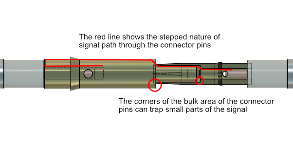
Connector discontinuities may introduce:
- reflections
- return loss
- insertion loss
- standing waves
¶ Copper Draw Down Process
The manufacturing process used to create the centre conductor affects RF performance.
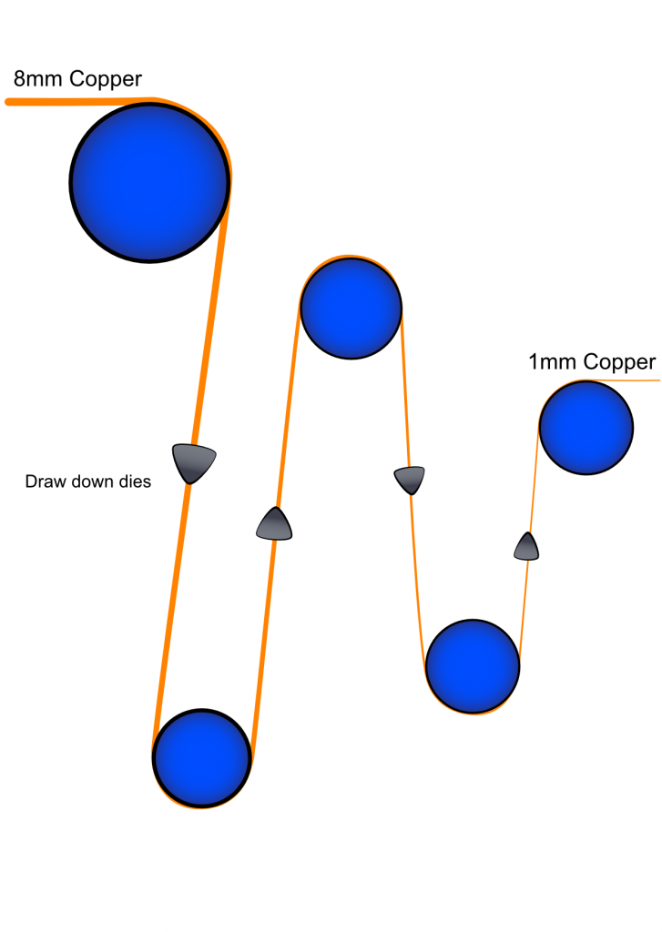
During manufacture:
- copper is mechanically drawn down
- tooling wear may create imperfections
- surface damage may affect RF performance
¶ RF Cable Dimensional Tolerances
Small dimensional variations can significantly affect RF behaviour.
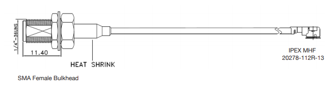
Manufacturing tolerances influence:
- impedance consistency
- return loss
- attenuation
- phase stability
¶ Core Surface Imperfections
The following image illustrates conductor surface imperfections.

Surface irregularities can:
- reflect RF energy
- increase return loss
- increase attenuation
- reduce efficiency
Important Note
Repeated imperfections over long cable lengths can significantly increase RF losses.
¶ Shielding Effectiveness
RF cable shielding protects the signal from external interference.
Common shielding methods include:
- foil shields
- braided shields
- foil and braid combinations
Shield quality affects:
- EMI rejection
- signal leakage
- susceptibility to interference
¶ External Interference Sources
Poor shielding may allow interference from:
- mains power cables
- switching power supplies
- motors
- inverters
- nearby RF transmitters
This may result in:
- corrupted packets
- retransmissions
- reduced throughput
- reduced receiver sensitivity
¶ Connector Quality
Connector quality plays a major role in RF system performance.
Poor connector quality may introduce:
- impedance mismatch
- insertion loss
- reflections
- poor long-term reliability
¶ Outdoor RF Connector Example
The following image shows a typical outdoor RF connector assembly.
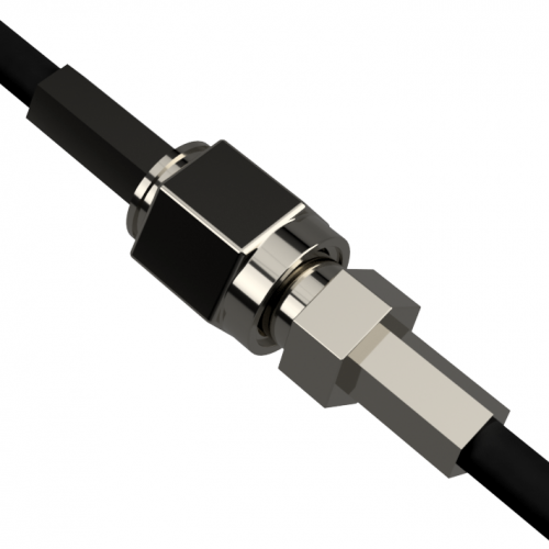
Outdoor installations should consider:
- vibration
- corrosion
- moisture ingress
- UV exposure
¶ Weatherproof Connector Sealing
Outdoor RF connections should be properly sealed against environmental exposure.
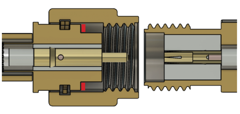
Improper sealing may lead to:
- water ingress
- corrosion
- increased attenuation
- connector failure
¶ Impedance Mismatch
Most RF systems use:
- 50Ω impedance
Impedance mismatch causes:
- reflected RF energy
- standing waves
- reduced power transfer
- increased losses
Maintaining consistent impedance throughout the RF path is critical.
¶ Return Loss
Return loss measures reflected RF energy caused by impedance discontinuities.
Poor return loss may:
- reduce transmitted power
- reduce receive sensitivity
- increase retransmissions
- reduce system efficiency
¶ Cable Bend Radius
Sharp cable bends can damage the cable structure.
This may:
- deform the dielectric
- distort shielding
- increase attenuation
- increase return loss
Best Practice
Maintain smooth cable bends and avoid kinks during installation.
¶ Avoid Excessive Adapters
Each additional adapter introduces:
- insertion loss
- impedance mismatch
- additional failure points
Avoid:
- unnecessary adapters
- multiple joins
- temporary connector chains
Where possible, use a single continuous cable assembly.
¶ Low Loss Cable Selection
For longer cable runs, low-loss cable should be used.
This becomes increasingly important for:
- LTE
- 5G
- GNSS
- WiFi
- high-frequency IoT systems
Low-loss cable helps:
- preserve signal strength
- improve throughput
- improve receiver sensitivity
- reduce retransmissions
¶ IoT Battery Life Impact
Poor RF performance can significantly affect battery-powered IoT devices.
Weak signals may cause:
- retransmissions
- longer modem active time
- increased current consumption
- reduced battery life
Example
A battery-powered IoT device expected to operate for several years may experience significantly reduced battery life if poor cable quality causes repeated retransmissions.
¶ Separation from Power Cables
RF cables should be separated from mains power cables wherever possible.
| Power Type | Recommended Separation |
|---|---|
| 240V AC | 100mm minimum |
| 415V AC | 300mm minimum |
This helps reduce:
- induced interference
- coupling
- transient noise
¶ Practical Installation Guidelines
| Guideline | Recommendation |
|---|---|
| Cable length | Keep cable runs as short as possible |
| Cable type | Use low-loss cable for longer runs |
| Adapters | Minimise additional adapters |
| Shielding | Use high-quality shielded cable |
| Bend radius | Avoid tight bends and kinks |
| Outdoor sealing | Protect external RF connections |
| Power cable routing | Maintain separation from mains cables |
¶ Key Takeaways
| Recommendation | Reason |
|---|---|
| Keep cable runs short | Reduces attenuation and signal loss |
| Use low-loss cable | Improves LTE, 5G and GNSS performance |
| Avoid unnecessary adapters | Reduces mismatch and insertion loss |
| Use quality connectors | Improves long-term reliability |
| Avoid tight bends | Protects cable geometry and shielding |
| Protect outdoor connections | Improves environmental reliability |
¶ Related Documents
- Successful Antenna Selection in Embedded IoT Applications
- Low Profile Antennas in IoT Applications
- Understanding 2D Radiation Plots
- Improving Cellular Signal Reception in IoT Applications
Reference Centre
Return to the Antenna Application Notes